LineStartup() Test Objective
The purpose of the LineStartup() test is to determine the converter response when the line voltage is suddenly switched on. The input is configured as an AC Startup Input Source, and the output is configured as a Resistive Load. The initial conditions for the simulation are typically found with a FindAcSteadyState() test, which runs a long transient simulation and saves the initial conditions using the GenerateInitFile testplan entry. For this test, the control input to the power supply is set to ON.
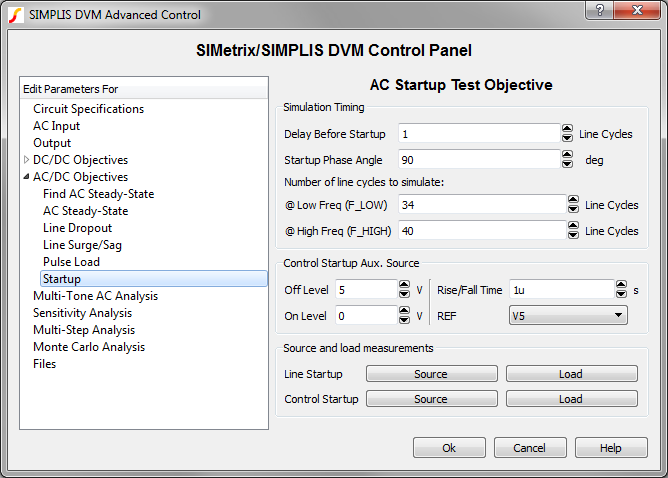
The LineStartup() test runs a transient simulation on the converter with the timing based on values entered in the Startup page, which is shown below and accessed from the Full Power Assist DVM control symbol.
This test objective measures the following scalar values:
- Frequency of Input Source
- Per Line Cycle Average of each output load voltage at:
- The start of the simulation
- The last line cycle of the simulation
- The second-to-the-last line cycle
- Percentage change in output load voltages over the final two line cycles
In this topic:
Testplan Syntax
The LineStartup() function has the following syntax with the arguments described in the table below:
LineStartup(REF, LINE_RANGE, VOLTAGE, FREQUENCY)
LineStartup(REF, LINE_RANGE, VOLTAGE, FREQUENCY, OPTIONAL_PARAMETER_STRING)
| Argument | Range | Description |
| REF | n/a | The actual reference designator of the DVM Source or the generic syntax of INPUT:n where n is an integer indicating a position in the list of DVM sources. |
| LINE_RANGE | LL or HL | The line range to select the correct symbolic voltage value. This can only be the two strings LL or HL. |
| VOLTAGE | min:0 | The RMS voltage for the input source. The voltage can be a numeric value or a symbolic value, such as a percentage of nominal input voltage. Symbolic values use the LINE_RANGE parameter to find the correct symbolic value. |
| FREQUENCY | min: > 0 | The AC line frequency of the input source. This is used to both set the frequency of the input source and to set the simulation timing. The frequency can be a numeric or a symbolic value, such as F_High or F_Low. |
| OPTIONAL_PARAMETER_STRING | n/a | Parameter string with a combination of one
or more timing parameters:
|
parameter_name1=parameter_value1 parameter_name2=parameter_value2The order of the parameter key-value pairs does not matter.
Simulation Timing
DVM sets the timing parameters for the LineStartup() test objective based on values that you enter on the StartupStartup page of the DVM Full Power Assist control symbol:
Delay Before Startup, Number of line cycles to simulate, and Startup Phase Angle.
In the OPTIONAL_PARAMETER_STRING and in the calculations below, these values are renamed as follows:
- NCYCLES_DELAY = Delay Before Startup
- NCYCLES_STOP = Number of line cycles to simulate. The GUI has two entries, one for each line frequency.
- PHASE_ANGLE = Startup Phase Angle
- LINE_PHASEANGLE is the phase angle of the line source. This can only be set using
the OPTIONAL_PARAMETER_STRING.Note: If a numeric frequency is provided, the program uses the @ High Freq (F_HIGH) entry to calculate the stop time.
The time delay is based on the following conditions and calculations. Typically the LINE_PHASEANGLE is set to 0, although in a 3 phase system only one of the three line sources will have a zero LINE_PHASEANGLE.
If LINE_PHASEANGLE is greater than 0, then
\[ \text{TIME_DELAY} = \frac{360 - \text{LINE_PHASEANGLE}}{360 * \text{FREQUENCY}} + \frac{\text{NCYLES_DELAY}}{\text{FREQUENCY}} + \frac{\text{PHASE_ANGLE}}{360 * \text{ FREQUENCY}} \]
If LINE_PHASEANGLE is less than or equal to 0, then
\[ \text{TIME_DELAY} = \frac{\text{NCYLES_DELAY}}{\text{FREQUENCY}} + \frac{\text{PHASE_ANGLE}}{\text{360} * \text{FREQUENCY}} \]
The stop time is calculated as:
\[ \text{STOP_TIME} = \frac{\text{NCYCLES_STOP}}{\text{FREQUENCY}}\]
Source and Load Subcircuit Configuration
The LineStartup() test objective sets the source and load subcircuits to the following:
| Source | Control Source (if used) | Load |
| AC Startup Input Source | DC Auxiliary Source | Resistive Load |
Loads other than the output under test are set to the Resistive Load. All other sources are set to either the DC Input Source for DC sources or the AC Fixed Input Source for the AC input sources.
Measured Scalar Values
The LineStartup() test objective measures the following scalar values where {load_name} is the name assigned to each load, and {source_name} is the name assigned to each source.
| Scalar Name | Description |
| Frequency({source_name}) | A number which represents the line frequency. |
| vout{n}_turn_on_time | The time required for the output voltage to reach the output voltage regulation band. |
| V{load_name}%_diff_last_2_linecycles | The percent change in the output voltage when averaged over the last two line cycles. |
| I{source_name} Inrush Current | The maximum current for the input source during the startup event. |
| V{load_name} At Simulation Start Time | The output voltage taken at time=0. |
| V{load_name} Last LineCycle | The average value of the output voltage during the last line cycle in the simulation. Used for the V {load_name} %_diff_last_2_linecycles calculation. |
| V{load_name} Previous LineCycle | The average value of the output voltage during the second to the last line cycle in the simulation. Used for the V {load_name} %_diff_last_2_linecycles calculation. |
| I{load_name} | Minimum and Maximum values of the load current. |
| V{load_name} | Minimum and Maximum values of the load voltage. |
| I{source_name} | Minimum, Maximum, and RMS values of the source current. |
| V{source_name} | Minimum, Maximum, and RMS values of the source voltage. |
| I{load_name} in Reg. | Average, Minimum, Maximum, and RMS values of the load current when the converter is in regulation. |
| V{load_name} in Reg. | Average, Minimum, Maximum, and RMS values of the load voltage when the converter is in regulation. |
Measured Specification Values
In the following table, {load_name} is the name assigned to each load, and {source_name} is the name assigned to each source.
| Scalar Name | PASS/FAIL Criteria |
| AC_Settling({load_name}) | The percentage change in the output load voltage over the final two line frequency cycles is less than the maximum specification value. |
| Max_{source_name}_Inrush | The converter passes if the maximum source current is less than the maximum source current inrush specification. |
| Max_V{load_name} | The maximum value of the output during the simulation time is less than the maximum specification value. |
| Max_V{load_name}_overshoot | The maximum overshoot value of the output during the simulation time is less than the overshoot specification value. |
| Min_V{load_name}_reg | The minimum value of the output at the end of the simulation time is greater than the minimum specification value. |
| Max_V{load_name}_reg | The maximum value of the output at the end of the simulation time is less than the maximum specification value. |
Testplan Example
An example of the LineStartup() test objective taken from the AC/DC (1-input/1-output) testplan is shown below. This test objective configures the input source to the low-line maximum symbolic value. The timing for the startup is determined by the values entered in the Startup page of the Full Power Assist DVM control symbol.
| *?@ Analysis | Objective | Source | Load | Label | GenerateInitFile | IncludeInitFile |
| Transient | LineStartup(INPUT:1, LL, Maximum, F_High) | Load(OUTPUT:1, 100%) | Transient|LineStartup|LL_Maximum|F_High|100% Load | INITFILE_HL_Maximum_F_Low_100% Load_Enabled |
Optional Parameter String
The following LineStartup() test objective uses the OPTIONAL_PARAMETER_STRING argument to modify the default simulation timing.
LineStartup(INPUT:1, LL, Maximum, F_High, NCYCLES_DELAY=2 NCYCLES_STOP=30 PHASE_ANGLE=45)
Test Report
You can view the complete test report in a new browser window here: LineStartup() Test Report. Below is an interactive link to the same test report.