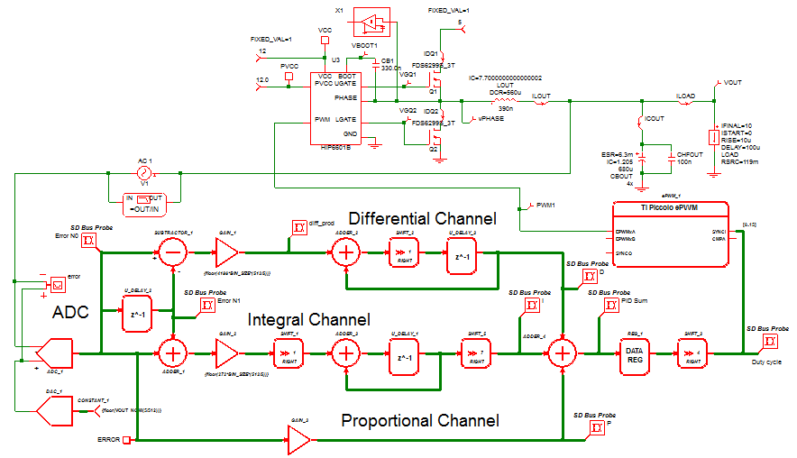
SIMPLIS SystemDesigner is a set of SIMPLIS schematic building blocks that are optimized to model digitally controlled, power electronics systems. These power electronics systems include both hardware and software digital-control implementations, such as control systems based on microcontrollers, DSPs, or FPGAs. An example of a PID control loop designed in SystemDesigner is depicted below:

Major features of SystemDesigner are:
- Time-sampled data in the digital-control-system signal path can be represented as signed integers with up to 32-bit precision or as double-precision floating-point numbers. In both cases, the control signals are discretely sampled as in the actual system, accurately modeling the phase-shift effects of the time-sampled data system.
- Integer data accurately represents the quantization error of the actual product implementation.
- Double-precision floating-point data represent the signal path magnitudes with "analog precision" and essentially eliminate any quantization error.
- A major advantage of modeling the time-sampled signal path with double-precision floating-point accuracy is that you can use the SIMPLIS POP and AC analyses on the digital control system. The speed and accuracy of this approach is valuable early in the design process.
- Each operation in the signal path (addition, multiplication, shift, etc.) can take a user-defined number of system clock cycles to complete in order to closely model the behavior of a software-based system.
- Clocks are distributed globally to all SystemDesigner blocks in the hierarchy. Treating clocks globally allows you to focus on the design task, rather than on connecting clock lines.
- A complete PWM generator based on the Texas Instruments Piccolo™ enhanced PWM (ePWM) module is included in SystemDesigner.
- This PWM module can generate almost any PWM pattern, including variable frequency (LLC) or phase-shifted topologies.
- The PWM generator can start an ADC conversion at any point in the PWM cycle, allowing you to accurately model the time-domain sampling behavior of the converter.
* Piccolo is a trademark of Texas Instruments Incorporated.
Synchronous Buck Converter Example
A digitally controlled Synchronous Buck converter using SystemDesigner devices is shown below. The complete PID control loop is defined using a collection of SystemDesigner control devices. The data in the control path is clocked using the SystemDesigner global clocks. This example circuit can be downloaded here. You will need a SIMetrix/SIMPLIS Pro or Elite license to edit and simulate this schematic. Evaluation licenses for SIMPLIS Pro and Elite may be requested either by email or through our evaluation page.
Synchronous Buck Converter Waveforms
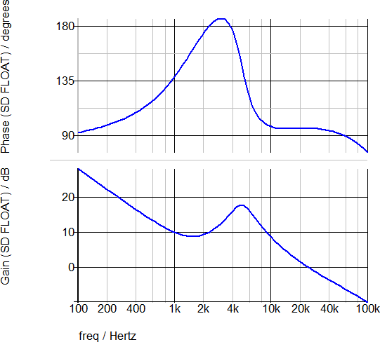
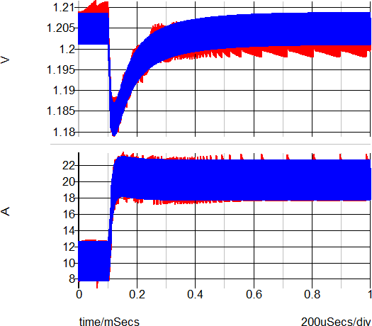
The output waveforms for the Integer sampled data type are sown in red below. On the left hand graph, the converter response to a 50%-100% load step is shown. The blue waveforms are from the Double-Precision Floating-Point sampled data type simulation. On the right hand graph is the AC analysis of the converter taken during the double precision floating point simulation. All waveforms were taken from the single schematic pictured above.
SystemDesigner Documentation
The SystemDesigner module is fully documented with example circuits in our documentation system. A good place to start is the SystemDesigner Tutorial.