
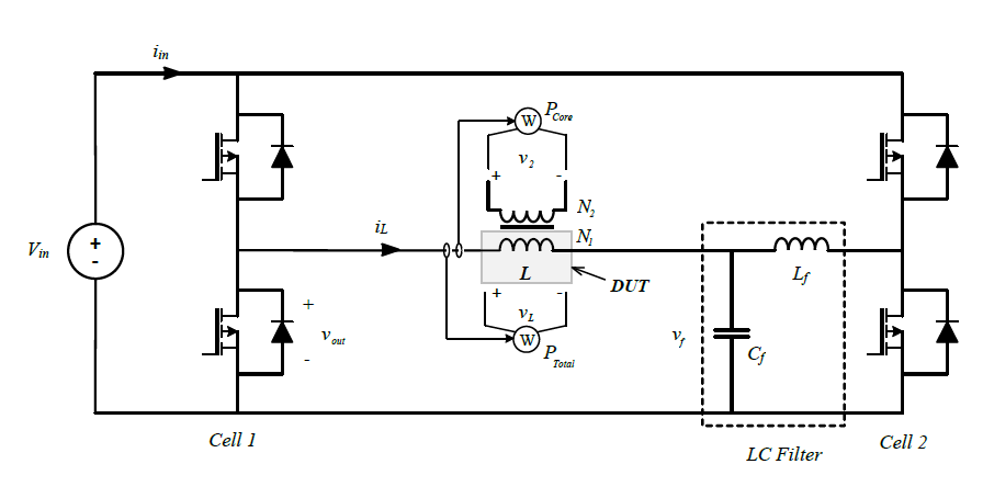
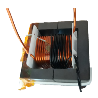
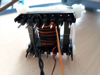
A number of inductors and transformers were constructed for the purpose of confirming the accuracy of the simulation results obtained using SIMPLIS MDM. A non-exhaustive list of measurements is given in this document. Measurements were completed at different times using varying measurement setups. In some cases, both losses and temperatures were measured, in some only losses. Where possible, core and winding losses were measured separately. Photographs of the measured devices are provided where available.
A PDF version of this article can be downloaded here.
Table of Contents:
- E-Core
- P-Core
- PM-Core
- ELP-Core
- Core and Winding Loss Measurments of E-Core Inductors
- Two-Winding E-Core Transformers
E-Core Inductor, Nominal L = 190.75 μH
| Core Material | EPCOS N27 Ferrite |
| Core | E55/28/21 |
| Air gap type | Center leg only |
| Air gap size | 1 mm |
| Turns | 18 |
| Wire type | Round Copper |
| Wire diameter | 1.7 mm |
Measurements with symmetrical triangular flux waveforms, zero DC bias
| ΔB (T) | f (kHz) | MDM Calculated Losses (W) | Measured Losses (W) | Relative Error (%) |
|---|---|---|---|---|
| 0.25 | 5 | 0.63 | 0.61 | 3.28 |
| 0.5 | 5 | 2.96 | 2.70 | 9.63 |
| 0.1 | 5 | 0.19 | 0.20 | -3.06 |
| 0.2 | 10 | 0.89 | 0.88 | 1.14 |
| 0.2 | 10 | 2.10 | 2.01 | 4.48 |
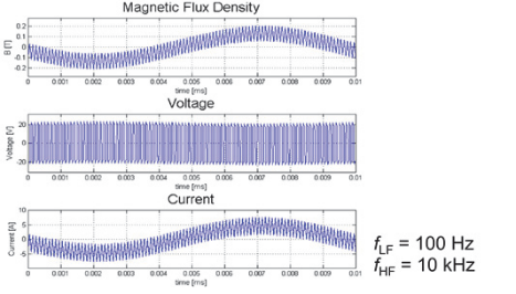
| LF ΔB (T) | HF ΔB (T) | MDM Calculated Losses (W) | Measured Losses (W) | Relative Error (%) |
|---|---|---|---|---|
| 0.25 | 0.15 | 0.79 | 0.76 | 3.95 |
| 0.50 | 0.30 | 3.35 | 3.60 | -6.94 |
▲ Back to Top ▲
Thermal Measurements of E-Core Inductors
| Core Material | EPCOS N87 Ferrite |
| Air gap type | Center leg only |
| Wire type | Round Copper |
| Nominal L | 85.66 μH |
| Core | E25/13/7 |
| Air gap size | 1.05 mm |
| Turns | 27 |
| Wire diameter | 0.8 mm |
| Nominal L | 88.77 μH |
| Core | E32/16/9 |
| Air gap size | 0.55 mm |
| Turns | 18 |
| Wire diameter | 0.8 mm |
| Nominal L | 526.94 μH |
| Core | E20/10/6 |
| Air gap size | 1 mm |
| Turns | 80 |
| Wire diameter | 0.45 mm |
Measurements with symmetrical triangular flux waveforms, zero DC bias
Inductor A
| Operating Point | ||
|---|---|---|
| ΔB = 0.3 T, f = 10 khz | ΔB = 0.3 T, f = 20 khz | |
| MDM Calculated Losses (W) | 0.47 | 0.73 |
| Calculated Core Temperature (°C) | 36 | 41 |
| Calculated Winding Temperature (°C) | 44 | 53 |
| Measured Losses (W) | 0.50 | 0.74 |
| Measured Core Temperature (°C) | 40 | 43 |
| Measured Winding Temperature (°C) | 49 | 58 |
| Relative Error ‐ Losses (%) | -6.00 | -1.35 |
| Relative Error ‐ Core Temp. (%) | -10.00 | -4.65 |
| Relative Error ‐ Winding Temp. (%) | -10.20 | -8.62 |
Inductor B
| Operating Point | ||
|---|---|---|
| ΔB = 0.3 T, f = 10 khz | ΔB = 0.3 T, f = 20 khz | |
| MDM Calculated Losses (W) | 0.45 | 0.65 |
| Calculated Core Temperature (°C) | 33 | 37 |
| Calculated Winding Temperature (°C) | 38 | 41 |
| Measured Losses (W) | 0.45 | 0.60 |
| Measured Core Temperature (°C) | 35 | 37 |
| Measured Winding Temperature (°C) | 43 | 45 |
| Relative Error ‐ Losses (%) | 0.00 | 8.33 |
| Relative Error ‐ Core Temp. (%) | -5.71 | 0.00 |
| Relative Error ‐ Winding Temp. (%) | -11.63 | -8.89 |
Inductor C
| Operating Point | ||
|---|---|---|
| ΔB = 0.3 T, f = 20 khz | ΔB = 0.4 T, f = 50 khz | |
| MDM Calculated Losses (W) | 0.40 | 1.66 |
| Calculated Core Temperature (°C) | 38 | 64 |
| Calculated Winding Temperature (°C) | 46 | 97 |
| Measured Losses (W) | 0.38 | 1.60 |
| Measured Core Temperature (°C) | 39 | 60 |
| Measured Winding Temperature (°C) | 46 | 91 |
| Relative Error ‐ Losses (%) | 5.26 | 3.75 |
| Relative Error ‐ Core Temp. (%) | -2.56 | 6.67 |
| Relative Error ‐ Winding Temp. (%) | 0.00 | 6.59 |
▲ Back to Top ▲
P-Core Inductor, Nominal L = 48 μH
| Core Material | EPCOS N87 Ferrite |
| Core | P30x19 |
| Air gap type | All three legs |
| Air gap size | 0.24 mm |
| Turns | 10 |
| Wire type | Round Copper |
| Wire diameter | 1.0 mm |
| ΔB (T) | f (kHz) | MDM Calculated Losses (W) | Measured Losses (W) | Relative Error (%) |
|---|---|---|---|---|
| 0.2 | 20 | 0.29 | 0.29 | 0.00 |
| 0.1 | 50 | 0.17 | 0.18 | -5.56 |
| 0.2 | 50 | 0.62 | 0.77 | -19.48 |
▲ Back to Top ▲
PM-Core Inductor, Nominal L = 981.53 μH
| Core Material | EPCOS N87 Ferrite |
| Core | PM50/39 |
| Air gap type | All three legs |
| Air gap size | 0.37 mm |
| Turns | 38 |
| Wire type | Round Copper |
| Wire diameter | 1.0 mm |
| ΔB (T) | f (kHz) | MDM Calculated Losses (W) | Measured Losses (W) | Relative Error (%) |
|---|---|---|---|---|
| 0.2 | 10 | 0.40 | 0.34 | 17.65 |
| 0.1 | 20 | 0.18 | 0.18 | 0.00 |
| 0.2 | 20 | 0.87 | 0.76 | 14.47 |
▲ Back to Top ▲
Thermal Measurements of PM-Core Inductor, Nominal L = 1.036 mH
| Core Material | EPCOS N87 Ferrite |
| Core | PM50/39 |
| Air gap type | All three legs |
| Air gap size | 0.6 mm |
| Turns | 48 |
| Wire type | Round Copper |
| Wire diameter | 1.5 mm |
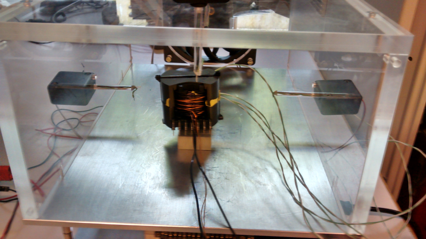
Thermal measurements in this and the following section were made using thermocouple sensors inserted into the windings and placed on the core surface, and in a chamber allowing for measurement of forced air flow from the cooling fan.
Measurements with symmetrical triangular flux waveforms, zero DC bias
| Operating Point | ||
|---|---|---|
| ΔB = 0.2 T, f = 10 khz | ΔB = 0.3 T, f = 10 khz | |
| Cooling Type | Natural convection | Forced convec., 3.5 m/s |
| MDM Calculated Losses (W) | 0.96 | 2.17 |
| Calculated Core Temperature (°C) | 29 | 29 |
| Calculated Winding Temperature (°C) | 38 | 45 |
| Measured Losses (W) | 1.01 | 2.38 |
| Measured Core Temperature (°C) | 35 | 31 |
| Measured Winding Temperature (°C) | 39 | 41 |
| Relative Error ‐ Losses (%) | -4.95 | -8.82 |
| Relative Error ‐ Core Temp. (%) | -17.14 | -6.45 |
| Relative Error ‐ Winding Temp. (%) | -2.56 | 9.76 |
▲ Back to Top ▲
Thermal Measurements of ELP-Core Inductor, Nominal L = 421.6 μH
| Core Material | EPCOS N87 Ferrite |
| Core | 2xELP64 |
| Air gap type | All three legs |
| Air gap size | 0.9 mm |
| Turns | 21 |
| Wire type | Round Copper |
| Wire diameter | 2 mm |
Measurements with symmetrical triangular flux waveforms, zero DC bias
| Operating Point | ||
|---|---|---|
| ΔB = 0.1 T, f = 10 khz | ΔB = 0.3 T, f = 10 khz | |
| Cooling Type | Natural convection | Forced convec., 2.5 m/s |
| MDM Calculated Losses (W) | 1.23 | 11.1 |
| Calculated Core Temperature (°C) | 31 | 43 |
| Calculated Winding Temperature (°C) | 33 | 59 |
| Measured Losses (W) | 1.01 | 8.8 |
| Measured Core Temperature (°C) | 28 | 38 |
| Measured Winding Temperature (°C) | 32 | 63 |
| Relative Error ‐ Losses (%) | 21.78 | 26.13 |
| Relative Error ‐ Core Temp. (%) | 10.71 | 13.16 |
| Relative Error ‐ Winding Temp. (%) | 3.13 | 6.35 |
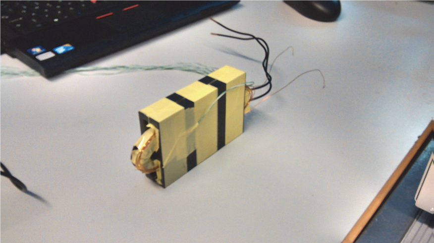
The error above 20% in the above measurements is due to relatively large proximity loss. Proximity losses are highly sensitive to the position of the windings relative to each other, the core, and especially the air gap. The experimental inductor with the ELP64 cores was built without a bobbin. Therefore, it was not possible to exactly match the winding position in the simulation and the measurement. To confirm this was the source of the error, losses were also measured at a much lower frequency where proximity losses were very low:
| ΔB (T) | f (kHz) | MDM Calculated Losses (W) | Measured Losses (W) | Relative Error (%) |
|---|---|---|---|---|
| 0.1 | 2 | 1.69 | 1.69 | 0.00 |
| 0.3 | 2 | 0.19 | 0.18 | 5.56 |
▲ Back to Top ▲
Core and Winding Loss Measurements of E-Core Inductors
A small secondary winding was used to measure core losses separately for two inductors. This measurement was subtracted from the total loss measurement to get winding losses.
Measurements with symmetrical triangular flux waveforms, zero DC bias
Inductor 1
| Nominal L | 344.62 μH |
| Core Material | EPCOS N27 Ferrite |
| Core | E55/28/21 |
| Air gap type | All three legs |
| Air gap size | 0.5 mm |
| Turns | 18 |
| Wire type | Round Copper |
| Wire diameter | 1.7 mm |
| ΔB (T) | f (kHz) | MDM Calculated Losses (W) | Measured Losses (W) | Relative Error | ||||
|---|---|---|---|---|---|---|---|---|
| Core | Winding | Total | Core | Winding | Total | Total (%) | ||
| 0.2 | 10 | 0.483 | 0.336 | 0.818 | 0.45 | 0.28 | 0.73 | 12.05 |
| 0.3 | 10 | 1.071 | 0.751 | 1.822 | 1.14 | 0.65 | 1.79 | 1.79 |
| 0.5 | 5 | 1.271 | 0.961 | 2.232 | 1.56 | 1.11 | 2.67 | -16.4 |
Inductor 2
| Nominal L | 144.33 μH |
| Core Material | EPCOS N87 Ferrite |
| Core | E32/16/9 |
| Air gap type | All three legs |
| Air gap size | 0.3 mm |
| Turns | 18 |
| Wire type | Round Copper |
| Wire diameter | 1.7 mm |
| ΔB (T) | f (kHz) | MDM Calculated Losses (W) | Measured Losses (W) | Relative Error | ||||
|---|---|---|---|---|---|---|---|---|
| Core | Winding | Total | Core | Winding | Total | Total (%) | ||
| 0.3 | 10 | 0.163 | 0.140 | 0.303 | 0.17 | 0.14 | 0.35 | -13.43 |
| 0.3 | 20 | 0.358 | 0.197 | 0.555 | 0.36 | 0.24 | 0.60 | -7.5 |
| 0.35 | 20 | 0.489 | 0.269 | 0.758 | 0.53 | 0.32 | 0.85 | -10.8 |
▲ Back to Top ▲
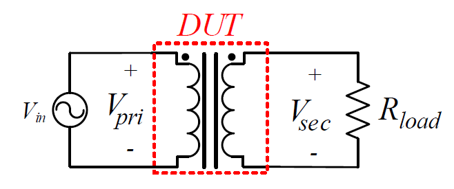
Two-Winding E-Core Transformers
The primary side of each transformer was excited with a sinusoidal voltage waveform, while the secondary side was loaded with a resistance selected to produce a desired output current.
| Nominal Lmag | 12.12 mH |
| Core Material | EPCOS N87 Ferrite |
| Core | E55/28/21 |
| Air gap type | All three legs |
| Air gap size | 0 mm |
| Turns Ratio | 22:11 |
| Wire type | Round Copper |
| Wire diameter | 1 mm, 1.2 mm |
| Nominal Lmag | 6.41 mH |
| Core Material | EPCOS N87 Ferrite |
| Core | E55/28/21 |
| Air gap type | All three legs |
| Air gap size | 0 mm |
| Turns Ratio | 16:2 |
| Wire type | Round Copper |
| Wire diameter | 1 mm, 1.4 mm |
| Nominal Lmag | 57.68 mH |
| Core Material | EPCOS N87 Ferrite |
| Core | E55/28/21 |
| Air gap type | All three legs |
| Air gap size | 0 mm |
| Turns Ratio | 48:10/td> |
| Wire type | Round Copper |
| Wire diameter | 0.5 mm, 0.85 mm |
Measurements with sinusoidal voltage excitation on the primary side, zero DC bias
| Transformer 1 | Transformer 2 | Transformer 3 | |
|---|---|---|---|
| Vin (V) | 10 | 48 | 24 |
| Iout (A) | 5 | 6 | 1 |
| f (kHz) | 1 | 25 | 50 |
| Calculated Loss (W) | 0.585 | 0.446 | 0.049 |
| Measured Loss (W) | 0.677 | 0.515 | 0.0435 |
| Relative Error (%) | -13.59 | -13.40 | 12.64 |
▲ Back to Top ▲