Analog to Digital Interfaces
At the simulator level, there are two types of node namely analog and digital and they cannot be connected together. At the netlist level it is possible to connect analog components to digital outputs and inputs. When SIMetrix sees an analog component connected to a digital signal, it automatically interconnects them using an interface bridge. It will use an analog-digital bridge to connect an analog signal to a digital input and a digital-analog bridge to connect to a digital output. If you connect an analog component to a signal which connects to both digital inputs and outputs both types of bridge will be used and the digital inputs and outputs will be separated from each other as illustrated in the following diagrams.
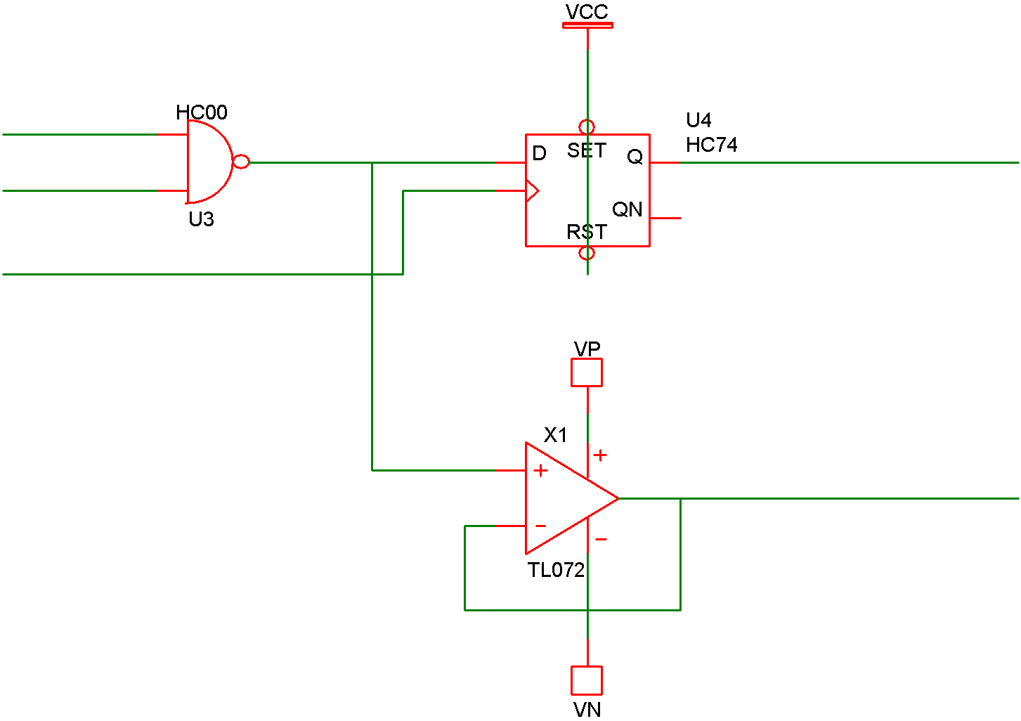 |
Circuit entered in schematic editor |
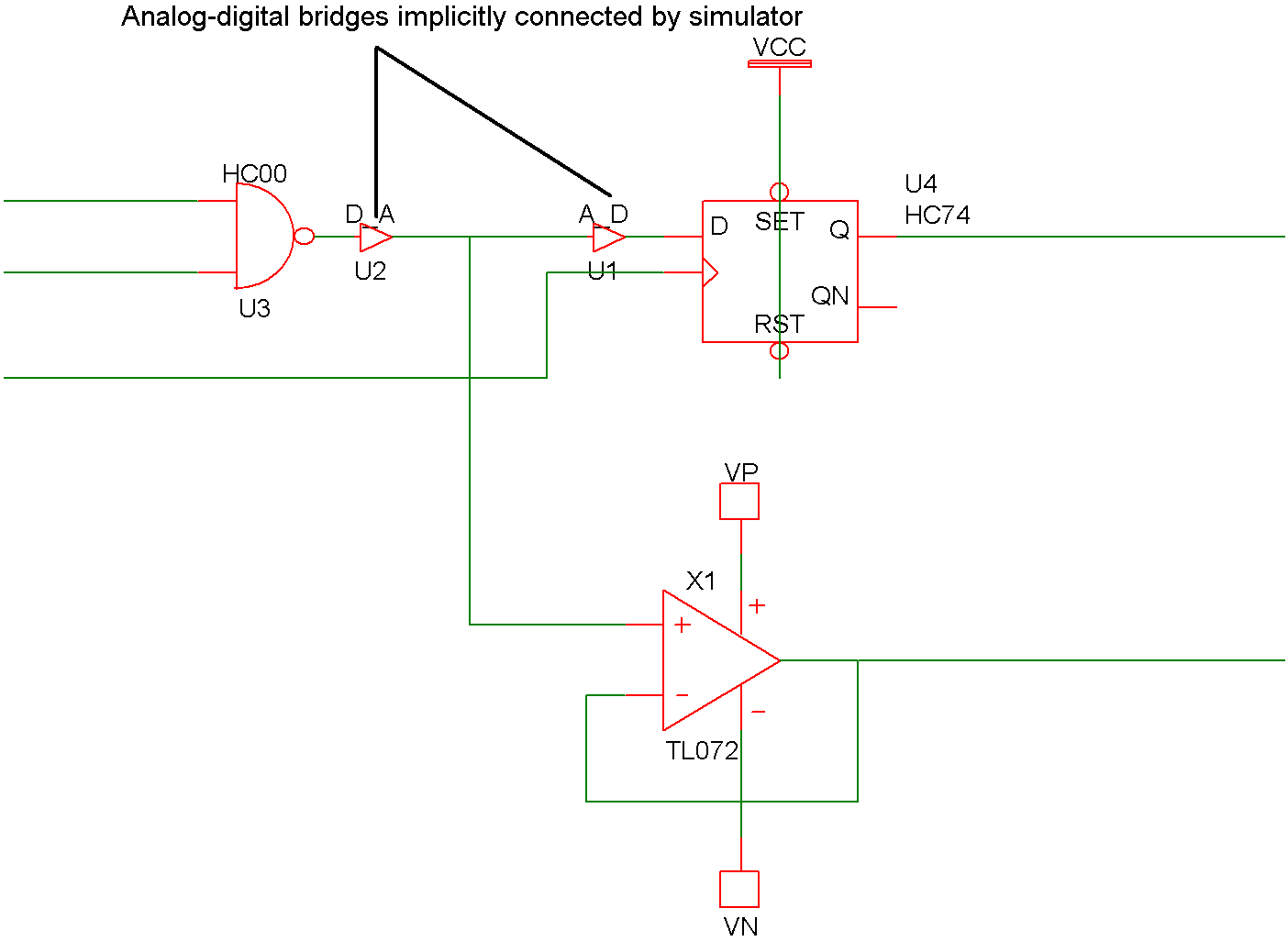 |
Circuit that is actually simulated |
In this topic:
How A-D Bridges are Selected
When SIMetrix implicitly places an AD bridge in a circuit, it must choose an appropriate model for the bridge. All AD bridges are based on DAC_BRDIGE and ADC_BRIDGE models described in Analog-Digital Interface Bridge, and Digital-Analog Interface Bridge. The model is chosen according to the FAMILY parameter assigned to the digital device to which the bridge is connected. The family parameters are listed below:
| Parameter name | Description |
| IN_FAMILY | Family for inputs |
| OUT_FAMILY | Family for outputs |
| FAMILY | Family for both inputs and outputs if IN_FAMILY/OUT_FAMILY not specified |
The name of the model used to interconnect digital to analog is always of the form:
family_name_dac
and to interconnect analog to digital
family_name_adc
For example if the family name is HC the D-A bridge is called HC_DAC. There is a selection of A-D and D-A bridges in the model library supplied with SIMetrix. (In BRIDGES.LB).
Variable Supply Voltage
The bridge devices are solely responsible for determining analog input thresholds and output levels. In real circuits, these parameters are affected by the supply voltage to the device. For this reason, most digital models feature a VSUPPLY parameter which can be set to the expected supply voltage for the part. The bridge device used to interface to the part will modify its input thresholds (A-D bridge) or output levels (D-A bridge) according to the VSUPPLY parameter and the bridge's VSUPPLY_NOMINAL parameter.
For more information refer to VSUPPLY Parameter
Multiple Inputs
If an analog signal is connected to multiple digital inputs from different devices, the inputs will be grouped according to the VSUPPLY and IN_FAMILY parameters. Each group with common VSUPPLY and IN_FAMILY parameter values will share a single bridge device.
Logic Compatibility
Some logic families are incompatible. For example, an ECL technology gate cannot directly connect to a CMOS gate as the voltage levels are incompatible. SIMetrix will detect this and issue an error should such a connection be made. SIMetrix determines the incompatibility by examining the output levels and input thresholds for the bridge models associated with the technology via the family parameters.
For example, if a 5V CMOS output is used to drive a 15V 4000-series CMOS gate, this error will be generated:
*** ERROR *** Logic incompatibility at node nodename : maximum output drive is 5V but
this is below the upper threshold of one or more connected inputs
The logic compatibility test can be disabled using this option setting:
.OPTIONS LogicTestCompatibility=0
Logic Compatibility - Legacy Mode
Versions 9.2 and earlier used a different system to determine logic compatibility based on a series of tables. This method is still available for backward compatibility. To enable this method add this option setting:
.OPTIONS LogicLegacyMode=1
For information about the legacy method, refer to the documentation for version 9.2 or earlier.
| ◄ Logic States | Load Delay ▶ |