Netlist to Schematic Converter
The Netlist to Schematic Converter creates a hierarchical schematic from a netlist. The schematic created is in the form of a grid of symbol instances representing each line in the netlist with terminal symbols to interconnect them. Symbols are automatically created to represent subcircuits and arbitrary sources. For arbitrary sources a symbol is generated that shows each voltage or/and current input. For subcircuits a symbol is created with pins for each terminal arranged on four sides. All current-carrying pins can be cross-probed making current flow studies straightforward.
An example of the output from the converter for a simple opamp is shown below:
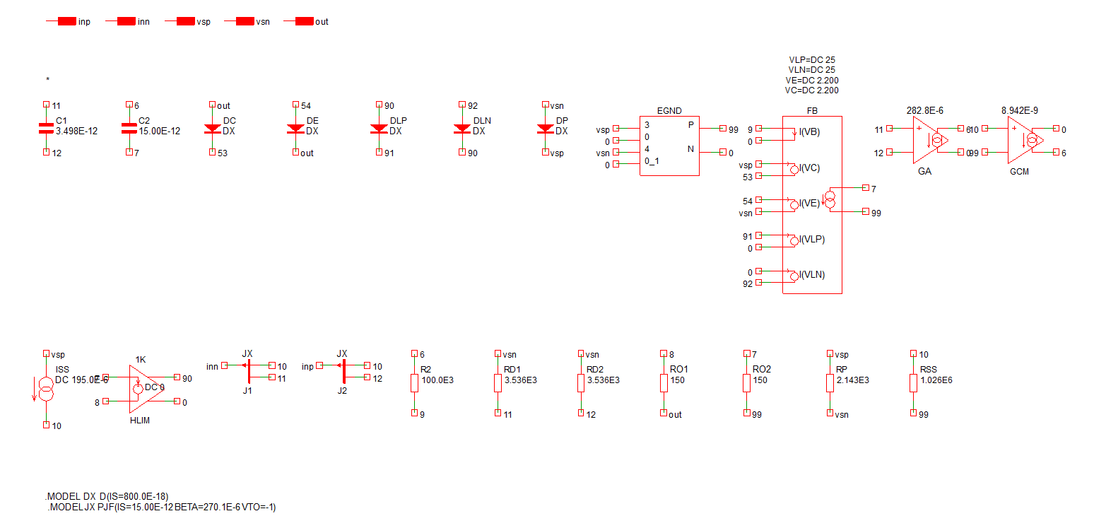
The following was obtained after manually rearranging and replacing terminal symbols with wires:
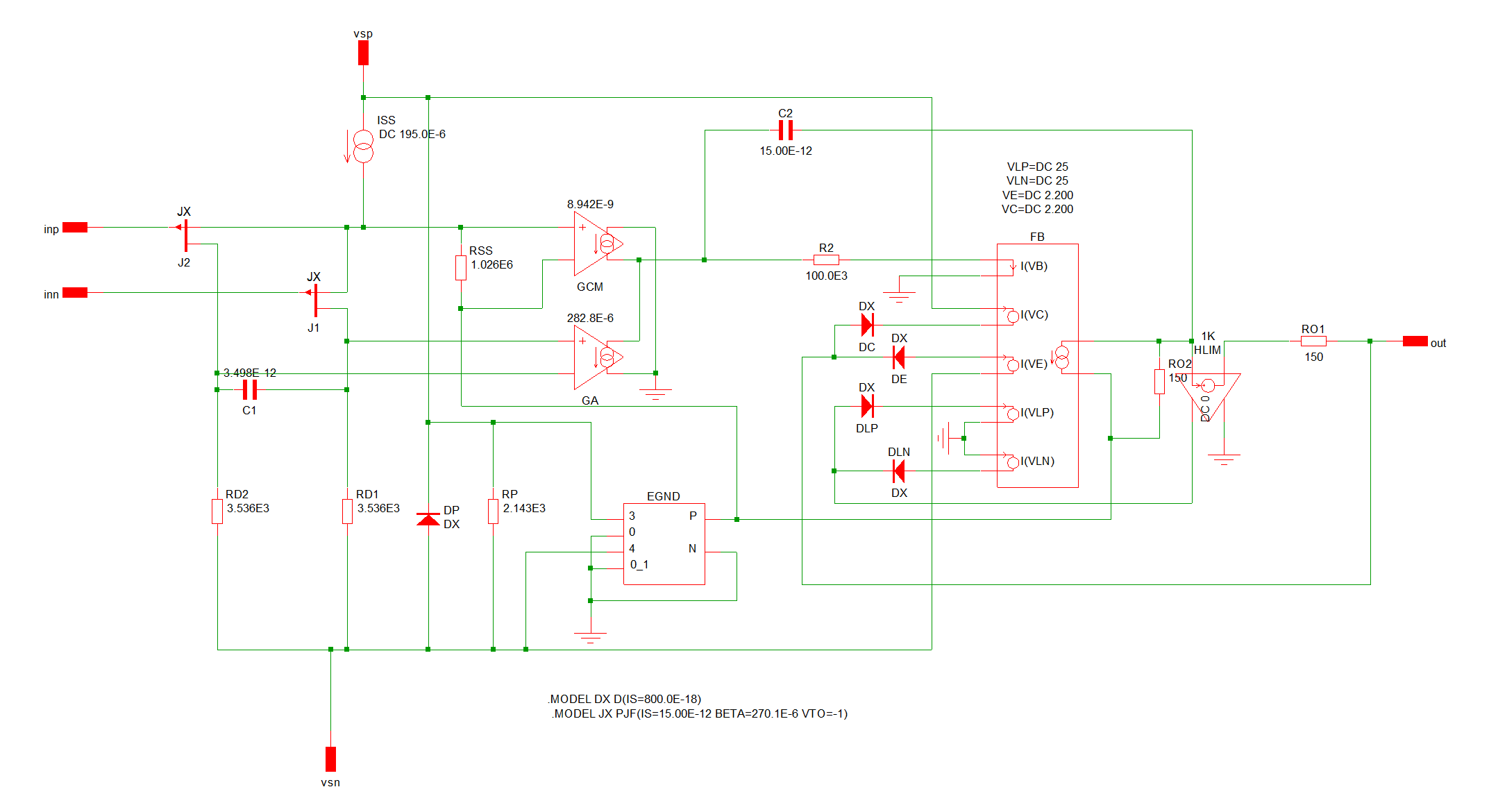
Netlist to Schematic Converter operates in one of two modes:
- Netlist mode. In this mode a complete netlist may be loaded. The resulting schematic will include all devices, parameters and analysis statements
- Model mode. In this mode an existing subcircuit model in a schematic can be converted. A hierarchical schematic for the model is created then the symbol representing the model in the parent schematic is modified to access the new schematic instead of the original model
The resulting schematic is built in a way that makes it simple to rearrange the various components in a conventional manner to aid readability.
Currently the Netlist to Schematic Converter supports SIMetrix schematics only.
The Netlist to Schematic Converter is useful for the following applications:
- Diagnosing problems with vendor models
- Modifying vendor models
- Importing schematics created for other simulators
In this topic:
Using the Netlist to Schematic Converter - Netlist Mode
- Select menu
- Navigate to a netlist file
-
If the conversion is successful, the schematic will open automatically. A message box similar to the picture below will also be shown:
 A report on the conversion process is created and can be opened by clicking the link in the message box. The report lists the schematic files created any files renamed to avoid overwriting. (See details below)
Using the Netlist to Schematic Converter - Model Mode
- Select model to be converted
- Right click menu Convert Model to Schematic
-
If the conversion is successful a message box similar to the picture below will also be shown:
 A report on the conversion process is created and can be opened by clicking the link in the message box. The report lists the schematic files created any files renamed to avoid overwriting. (See details below)
Simulating the Converted Schematic
In most cases the generated schematic will simulate identically to the original netlist. In some cases, the netlist created by the generated schematic is ordered differently to the original netlist and this may lead to subtly different results. This happens when current sensing devices are integrated with controlled sources as explained in Current Sensing Devices.
Notes
File Overwriting
If the conversion process is repeated, it will be necessary to overwrite files created in earlier conversions. A possibility could arise that some considerable manual work is done on a generated schematic then saved under the same name. This work would be lost if the schematic is overwritten by the converter. For this reason, a flag is stored in generated schematics which is cleared when manually modified. The converter will make a backup of modified schematics so that any manual work will not be lost. The backed up schematic will have a name in the form drive:dir/file.n.ext where n is a number between 1 and 3. So up to 3 backups will be retained at any time.
The report compiled in the conversion process will list any files backed up in the process.
Arbitrary Sources
Arbitrary Sources are used extensively in many models. These are either voltage sources or current sources with one or more voltage or/and current inputs. At the netlist level the inputs are referenced in an equation. The converter will build a special symbol for each arbitrary source and represent each input on the left hand side of the symbol with the output on the right or at the top (+) and bottom (-). An example is shown below:
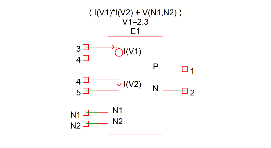
E1 1 2 VALUE = { I(V1)*I(V2) + V(N1,N2) }
V1 3 4 2.3
V2 4 5 0
The arbitrary sources uses voltage sources V1 and V2 as current sensors. The symbol created will incorporates these voltage sources which will not appear as separate sources in the schematic. Note in the above symbol that V1 is represented by a circle whereas V2 is a straight line with a current direction arrow. The circle is used for non-zero sources; the single arrow is used when the source is zero-volts which is often the case. The value of the source will be shown as a property above the symbol (V1=2.3 in this example).
Current Sensing Devices
Some models use current controlled sources either simple controlled voltage or current sources or arbitrary sources. In all cases a current sensing device is required which is usually a voltage source but can also be an inductor or a controlled voltage source. If the current sensor is a voltage source or inductor, the sensor will be incorporated as part of the symbol for the controlled source. For example, the following netlist lines:
F1 1 0 V1 1
V1 2 3 0
would be represented by this symbol:
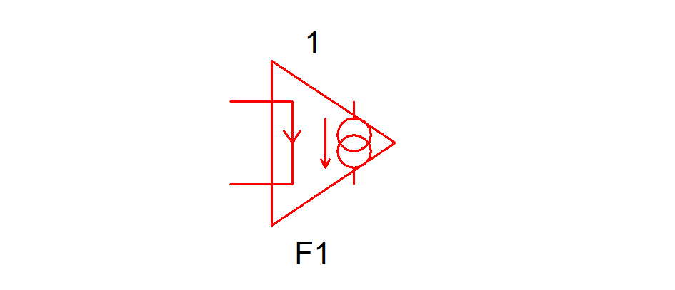
The voltage source V1 is represented by the input with the current direction arrow. That is both F1 and V1 lines in the netlist will be represented by the above symbol.
In some cases the voltage source will have a non-zero value. In that case the symbol will look like this:
A few models have multiple controlled sources that share a current sensor. For example:
F1 1 0 V1 1
F2 2 0 V1 1
V1 3 4 0
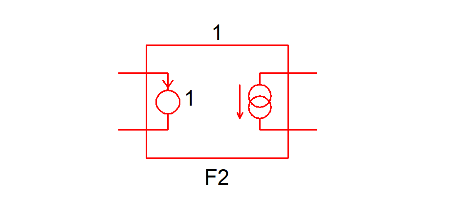
The above would be represented by the following:

In the above only F1 incorporates the V1 voltage source. F2, whose input is represented by a broken line does not include V1 but references it indirectly. For convenience, F2 is configured so that if the current into its inputs is probed, the plotted value will be the correct V1 current. However this current does not actually flow into the input of F2 but is used by F2 to control its output current. Electrically the circuit as a whole will behave correctly and identically to the original netlist.
Unsupported Devices
If the converter encounters netlist line that it is not able to represent in graphical form, it will simply reproduce the text as a control block. Electrically this will have the correct behaviour. A warning message will be displayed if this happens.
Customising Symbols
Any subcircuit instances encountered will be represented by a symbol in the same way as all other devices. If the subcircuit model is installed in the global library AND is associated with a symbol AND is at the top level in netlist mode, the associated symbol will be used.
In other situations a symbol will be auto-generated but it is possible to replace the auto-generated symbol with a user-designed symbol. The procedure for this is as follows:
- Run the converter in the normal way allowing it to auto-generate any subcircuit symbols
- Open the schematic with the symbols to be edited
- Select right-click menu Edit Symbol to open the symbol in the symbol editor
-
Edit the symbol in the usual way ensuring that
- The symbol's internal name remains unchanged. The internal name is not random and is formed from a combination of the model name and a hash of the model's terminal names
- The symbol's pin names are retained
- The symbol's TEMPLATE property value and any property it references (i.e. enclosed with '%') is not changed
- Save the symbol to an installed library file. Do not save to the schematic or as a component
- Repeat the conversion. The converter will detect the symbol by its name and use that version instead of an auto generated symbol
Copying and Pasting from a Converted Schematic
While it is usually possible to copy and paste a symbol from a schematic created from a netlist or model, this cannot be guaranteed to be always the case, especially when copying controlled sources with input currents. This is because the current sensing device (e.g. voltage source) may clash with an existing device on the receiving schematic.
| ◄ LTspice® Compatibility | Load Component Values ▶ |