2.2 Edit Standard Component Values
This section of the tutorial explains how to edit standard components. You will start with the schematic that you saved in 2.1 Add Symbols and Wires and then change the component values to more accurately reflect a practical design.
In this topic:
What You Will Learn
In this topic, you will learn the following:
- How to edit symbols and change values for standard components.
- How to change probe labels.
- How to configure the waveform generator.
2.2.1 Change Component Values
The full load current for this design is 10A and the output voltage is 1.2V. The load resistance is therefore 120mΩ. To change the resistance of the output load resistor, follow these steps:
- Double click the R1 symbol, making sure that you have the cross hair on the
symbol and not on the label. Result: The Choose Component Value dialog box opens.
- Change the value in the Result field to 120m as shown below.
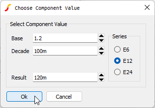
- Click Ok.
- Repeat steps 1 to 3 to edit two symbols and change the values as listed below:
Reference Designator Component Name New Value R2 Gate Resistor 1.5 V1 Input Source 12
2.2.2 Change Probe Curve Labels
Although not strictly necessary from an electrical perspective, the curve labels should be renamed to indicate which circuit variables are represented on the graph waveforms.
To rename the probe curve labels, follow these steps:
- Double click the probe symbol with label Probe1-NODE. Result: The Edit Probe dialog opens.
- In the Curve label text box, change the name to VOUT.
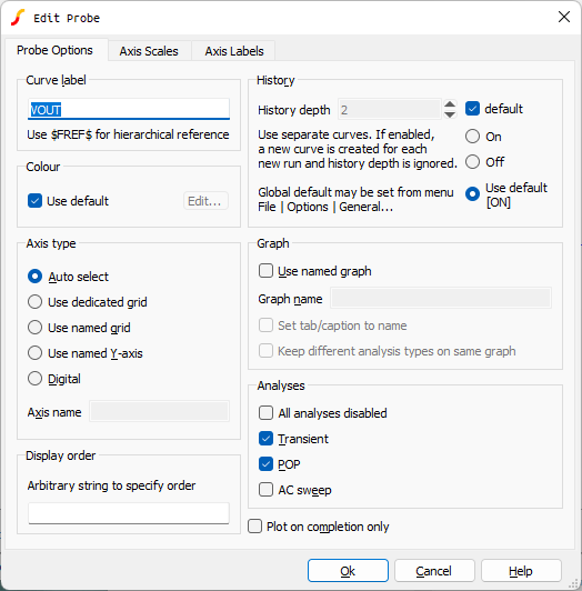
- Click Ok.
- Repeat steps 1 and 2 to change the curve labels for the other two probes as
indicated below:
Old Curve Label Circuit Variable New Label Probe2 NODE Switching Node SW IPROBE1 Inductor Current Probe IL
2.2.3 Configure the Waveform Generator
The waveform generator is a flexible device that can represent a number of periodic waveform types. To drive the MOSFET Q1, you need a pulse generator with a specified pulse width, frequency, and amplitude.
To set up the waveform generator as a pulse source, follow the steps below.
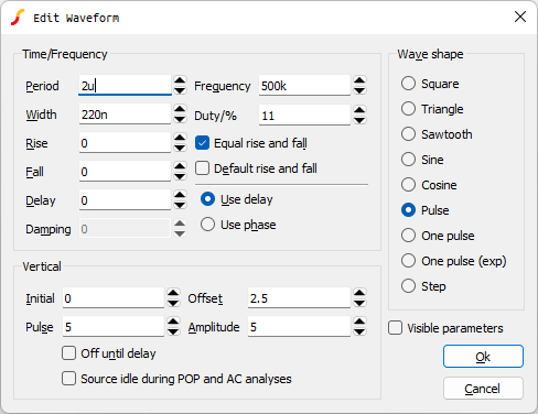
- Double click V2, the waveform generator symbol. Result: The Edit Waveform dialog opens.
- On the right side of the dialog in the Wave Shape section, select the Pulse radio button.
- In the middle column at the top, change Frequency to 500k and Duty
Cycle to 11.Note: The Edit Waveform Dialog is interactive, which means that as you make changes to certain fields, values for related fields are automatically calculated and updated. For example, after you change the Frequency to 500k, the Period is calculated and updated to 2u. The calculated values update on the dialog when you move the mouse to a new field.
- In the first column near the bottom of the dialog, change Pulse to 5.
- Deselect the Default rise and fall check box.
- In the Rise field, enter 0 to set a zero rise time.Result: The Edit Waveform dialog should now look like this:
- Click Ok to save the new parameter values.
The design is now at a point where you can start your first simulations and then begin further optimization.
2.2.4 Save your Schematic
To save your schematic, follow these steps:
- Select .
- Navigate to your working directory where you are saving your schematics.
- Name the file 2_my_buck_converter.sxsch.Note: You will use this schematic in the next section, 2.3 Edit Multi-Level Models.