PWL Resistors
The SIMPLIS Piecewise Linear (PWL) Resistor is used to model a broad variety of circuit elements. At its most basic, a PWL Resistor can model a pure resistor or perhaps include some resistance dependence on applied voltage or current.
An example of a more complex device would be a voltage clamp, where the current is quite small (high resistance) until a certain clamp voltage is reached, where the device has a low resistance in series with the clamp voltage. A quite complex example would be a constant power load, where the PWL resistor models a constant power dissipation within some defined voltage range.
A good description of the PWL modeling techniques using PWL resistors can be found at the SIMPLIS is Always Piecewise Linear, All the Time
In this topic:
Circuit Examples
Device Types: Voltage Controlled (VPWL) and Current Controlled (IPWL)
There are two SIMPLIS PWL resistor models, a voltage controlled PWL resistor (VPWL) and a current controlled PWL resistor (IPWL). To determine which device you need for your application, consider the type of curve you are modeling in the current versus voltage plane. If your curve has a single current value for every voltage, use the voltage controlled VPWL resistor. In this case, i = f(V). On the other hand, if your curve has a single voltage value for each current, use the current controlled IPWL resistor. This device has the function v = f(i). For a voltage controlled VPWL resistor, the voltage points must be continuously increasing, and for a current controlled IPWL device, the current points must be continuously increasing.
Possible Resistance values for each device and limitations
Negative Resistance
One of the more powerful features of the PWL resistor is the ability to model a negative resistance. This is typically required to accurately model the load presented by the input terminals of a switching power converter. Any number of the resistance segments can have negative resistance, except the first and last segments. These segments must have positive (non zero) resistance.
Zero and Infinite Resistance
Infinite resistance can also be modeled using the VPWL Resistor. Zero Resistance can be modeled using a IPWL device. Because the two special cases of zero and infinite resistance require different models, it is not possible to define a single device which switches between infinite and zero resistance.
Defining the PWL Resistor
A PWL resistor is defined using X-Y coordinates on the I-V plane. SIMPLIS will effectively draw a straight line between the first two points and extend that line out to minus infinity on the x axis. SIMPLIS will similarly draw a straight line between the last two points and extend that line out to positive infinity on the x-axis. In this way, the PWL resistor is defined over all possible values of the controlling variable.
There are two common ways to define your device. The first is to enter text directly into the Define PWL Resistor Dialog. The second is to use a spreadsheet to calculate the I-V values, and to copy them to your clipboard from the spreadsheet and then paste them into the dialog using the Paste button.
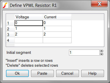
| Voltage | This column defines the Voltage points of your PWL Resistor |
| Current | This column defines the Current points of your PWL Resistor |
| 1, 2, 3, ... | Each row in the table represents a I, V Pair of coordinates |
| Paste | Use this button to paste ASCII data from a spreadsheet |