4.2 Reorder the Graph Grids
This section of the tutorial deals with the order of the grids in the waveform viewer.
In this topic:
Key Concepts
This topic addresses the following key concepts:
- The default grid, which in this case contains the SW curve, is always the lowest grid in the waveform viewer. The default grid cannot be deleted, but it can be empty; that is it has no curves plotted on it.
- Grids other than the default grid are ordered from top to bottom by alphanumerically sorting the curve names on the grid. The order of the grids up to this point in the tutorial is determined by the curve names: IL and VOUT, with the IL grid appearing above the VOUT grid. You can change this order by assigning an arbitrary string to the probe symbol, the sorting algorithm will use this string in place of the curve name.
What You Will Learn
In this topic, you will learn the following:
- How to change the vertical order of graph grids from:
- IL
- SW
- VOUT
- VOUT
- IL
- SW
4.2.1 Change the Grid Order
To change the order of the grids, use the 7_SIMPLIS_tutorial_buck_converter.sxsch example from section 4.1 Output Curves to Separate Grids and follow these steps:
- Close the waveform viewer; return to the schematic editor and double click the VOUT probe.
- In the Display order section in the lower left corner below Arbitrary
string to specify order, type A in the text box.
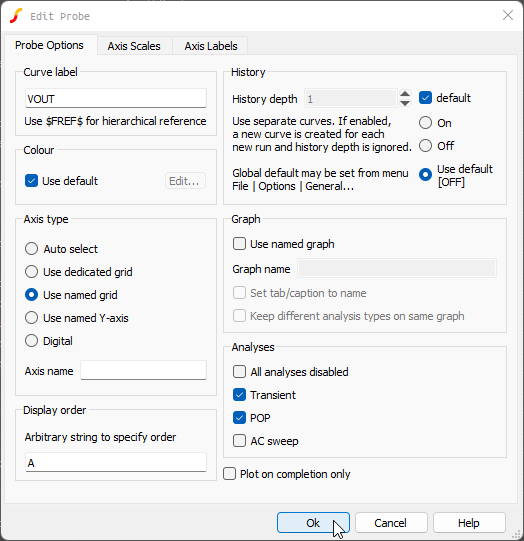 Note: Since the SW curve is on the default grid, you do not need to specify the order for the SW probe.Note: Any string which is alphanumerically less than IL will move the VOUT grid above the IL grid. The sort algorithm is case insensitive.
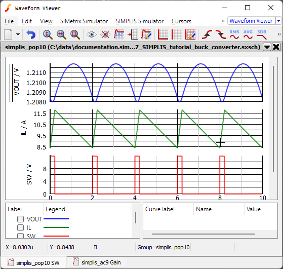
 - Click Ok, and then press F9 to rerun the simulation.Result: The new waveform viewer should now have the curves in the new order with VOUT above IL.
4.2.2 Save your schematic
To save your schematic, follow these steps:
- Click anywhere in the schematic to bring the schematic viewer in to focus.
- Select .
- Navigate to your working directory where you are saving your schematics.
- Name the file 8_my_buck_converter.sxsch.
A schematic saved at this state can be downloaded here: 8_SIMPLIS_tutorial_buck_converter.sxsch.