Control Statements for Printing Variables
There are two control statements that provide the ability to select data output by SIMPLIS. These are .PRINT and .KEEP. These are detailed in the following sections.
In this topic:
The .PRINT statement is used to specify the output variables to be recorded for printing/plotting. Note that with the SIMetrix/SIMPLIS, .PRINT only specifies data to be saved in the binary file and does not create ASCII tabular output. .PRINT instructs SIMPLIS to send the specified data to the SIMetrix front end. SIMetrix saves the data as a vector in its binary file. The actual vector name used is described in the following paragraphs.
The format of .PRINT is:
.PRINT var1 var2 ...where var1, var2, and ... are legal print variables. Forms of legal print variables and their meanings are listed below:
| V(DName) | Branch voltage across a two-terminal device in the current circuit. DName is the device name of a device whose element keyword is one of the following: R, L, C, V, I, E, G, H, F, Q, S, !R, !L, and !C SIMetrix vector name will be DName. |
| V(#NodeName) | Voltage on mapped node NodeName. Mapped nodes are created using the .NODE_MAP statement. SIMetrix vector name will be #NodeName. |
| I(DName) | Branch current through a two-terminal device in the current circuit. DName is the device name of a device whose element keyword is one of the following: R, L, C, V, I, E, G, H, F, Q, S, !R, !L, and !C SIMetrix vector name will be of the form: DName#pinname where pinname will be p for the first pin and n for the second pin. |
| I(DName#pinname) |
Current through a device pin. DName is the device name while pinname is either a pin number or mapped pin name. If Dname is a subcircuit device and the subcircuit definition includes .NODE_MAP statements to map its external nodes to names, then those mapped names may be used for pinname. For example:
X1 1 2 3 SUB1
.SUBCKT SUB1 100 200 300
.NODE_MAP INP 100
.NODE_MAP INN 200
.NODE_MAP OUT 300
...
...
.ENDS SUB1

.PRINT I(X1#INP)
The above .PRINT will instruct SIMPLIS to output the current into pin connected to node 1 of X1. The resulting SIMetrix vector will be called "X1#INP". |
| V(Node1,Node2) | Differential voltage from node Node1 to node Node2 where Node1 and Node2 are node names in the current circuit. |
| V(Node1) | Voltage from Node1 to node 0, the ground node. This form is allowable only in the main circuit and only if node 0 is present in the main circuit. SIMetrix vector name will be: Node1 |
| V(Xname1.Xname2.DName) | Branch voltage across the device named DName in the subcircuit referred to as Xname2 in the subcircuit referred to as Xname1 in the current circuit. The allowable device is same as those listed for the form of V(DName). SIMetrix vector name will be: Xname1.Xname2.DName |
| I(Xname1.Xname2.DName) | Branch current through the device named DName in the subcircuit referred to as Xname2 in the subcircuit referred to as Xname1 in the current circuit. SIMetrix vector name will be of the form: Xname1.Xname2.DName#pinname where pinname will be p for the first pin and n for the second pin. |
| V(Xname1.Xname2.Node1,Node2) | Differential voltage from node Node1 to node Node2 where Node1 and Node2 are node numbers in the subcircuit referred to as Xname2 in the subcircuit referred to as Xname1 in the current circuit. |
| NODE_V | Print all node voltages in the main circuit with respect to the ground node, node 0, in the main circuit. |
| ALL | Print all node voltages in the main circuit with respect to the ground node, node 0, in the main circuit and print all branch currents of the two-terminal devices in the main circuit. The two-terminal devices refer to those whose branch current can be printed through the form of I(DName). |
If the print variable NODE_V or ALL is used, then node 0 must be present in the main circuit. Although the number of output variables that are associated with NODE_V or ALL are obviously large, NODE_V or ALL is counted as one print variable in counting towards the maximum number of 200 print variables allowed in one simulation. Simulation can be substantially slower with NODE_V or ALL as a printing variable. In addition, if ALL is used as the print variable, other print variables defined in the main circuit, or in any of its descendant subcircuits, are ignored.
There are two subtle points that need to be understood when figuring out the SIMetrix vector names. If DName or Xname as appeared in the .PRINT statement is a device/subcircuit name containing a dollar sign '$', then all characters ahead of the first dollar sign and the first dollar sign are stripped in the corresponding DName or Xname in the SIMetrix vector name. For example, the following .PRINT statement
.PRINT I(X$U12.XABC.R234)
will result in a SIMetrix vector name of:
U12.XABC.R234#p
In addition, the SIMetrix vector names shown for each type of print variables above assume the .PRINT statement is defined in the top-level circuit/schematic. If the .PRINT statement is defined in a subcircuit/component schematic, then the actual SIMetrix vector name will be prepended by a path prefix. Let us take the following two .PRINT statements as examples:
.PRINT V(#VOUT)
.PRINT I(X$U12.XABC.R234)
If these .PRINT statements were defined in the top-level circuit/schematic, the SIMetrix vector names would be #VOUT, and U12.XABC.R234#p, respectively. Suppose the subcircuit/component schematic containing these two .PRINT statements is two-level down from the top-level circuit/schematic. In addition, suppose that the subcircuit/component schematic containing these two .PRINT statements can be reached from the top-level schematic by first descending into a component schematic named "Component A" with a reference designator of U76 and then descending into a component schematic named "Component B" with a reference designator of U34 as shown in the figure below.
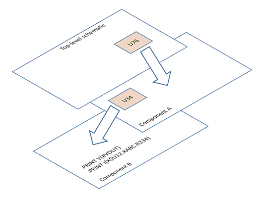 The SIMetrix vector names associated with the same two .PRINT statements would then be U76.U34.#VOUT and U76.U34.U12.XABC.R234#p, respectively.
.KEEP
The purpose of the .KEEP statement is to instruct SIMPLIS in a very generic way to produce and save voltages/currents for printing/plotting in the subcircuits/child components, thus enabling the debugging of the sucbircuits/child component schematics through random probing without knowing in advance what specific voltages/currents needed to be produced and kept for printing/plotting. Similar to the .PRINT statement, the .KEEP statement in the SIMetrix/SIMPLIS environment only specifies data to be saved in the aforementioned binary file and does not create the ASCII tabular output.
The format of .KEEP is:
.KEEP keep_var1, keep_var2, ...where keep_var1, keep_var2, and ... are legal keep variables.
Multiple .KEEP statements may be defined in a subcircuit/schematic. Forms of legal keep variables and their meanings are listed below:
| *V | All node voltages in the current circuit/schematic. With this keep variable specified, all node voltages in the current/schematic are produced and saved for printing/plotting. This keep variable is allowed only if node 0 is present in the top-level circuit/schematic because the node voltages are measured with respect to the voltage of node 0 in the top-level circuit/schematic. The SIMetrix vector names for the node voltages generated by the *V keep variable will be same as the SIMetrix vector names for the node voltages generated through .PRINT statements. So a node with a node number of NodeNum without any node mapping will result in a node voltage whose SIMetrix vector name is NodeNum, plus a path prefix if this node is not in the top-level schematic. Similarly, a node mapped to a name of NodeName will result in a node voltage whose SIMetrix vector name is #NodeName, plus a path prefix if this node is not in the top-level schematic. |
| *I | All printable/plottable currents for the current circuit/schematic. With this keep variable specified, all branch currents through two-terminal devices in the current circuit/schematic and all pin currents for subcircuit devices in the current circuit/schematic are produced and saved for printing/plotting. The SIMetrix vector names for the currents generated by the *I keep variable will be same as the SIMetrix vector names for the currents generated through .PRINT statements. So the SIMetrix vector name for a branch current will have the form of DName#pinname, where DName is the device name, and pinanme will be p for the first pin and n for the second pin. If the device is not in the top-level schematic, the SIMetrix vector name will have a path prefix. Similarly, the SIMetrix vector name for a subcircuit pin current will have the form of DName#pinname where DName is the device name, and pinname is either a pin number or a mapped pin name. Again, the SIMetrix vector name will have a path prefix if the device DName is not placed in the top-level schematic. |
| **V | This is similar to the *V keep variable used for producing node voltages. Specifying **V as a keep variable in the current circuit/schematic is equivalent to specifying *V in the current circuit/schematic and in all its descendant subcircuits/schematics. Hence, it will produce node voltages for the current circuit/schematic and all its descendant subcircuits/schematics for printing/plotting. Similar to the *V keep variable, this keep variable is allowed only if node 0 is present in the top-level circuit/schematic. For a very large hierarchical design, having the **V keep variable defined in the top-level schematic could result in a large number of print/plot variables and can lead to substantially slower simulations. |
| **I | This is similar to the *I keep variable used for producing branch and device pin currents. Specifying **I as a keep variable in the current circuit/schematic is equivalent to specifying *I in the current circuit/schematic and in all its descendant subcircuits/schematics. Hence, it will produce branch currents through two-terminal devices and subcircuit pin currents for the current circuit/schematic and all its descendant subcircuits/schematics for printing/plotting. For a very large hierarchical design, having the **I keep variable defined in the top-level schematic could result in a large number of print/plot variables and can lead to substantially slower simulations. |
| ◄ Control Statements for Setting Initial Conditions | Mapping Names to Node Numbers ▶ |