Fundamentals
In this topic:
Schematic Windows and Sheets
Schematic editor windows are Content Views in the SIMetrix GUI Environment. See SIMetrix GUI Environment.
Creating Schematics
- To create an empty SIMetrix schematic, select menu
- To create an empty SIMPLIS schematic, select menu
If you have a SIMetrix-only product use menu .
Changing Simulator Mode
If you have SIMetrix/SIMPLIS and you change the simulator mode, select menu where xxx is either SIMetrix or SIMPLIS.
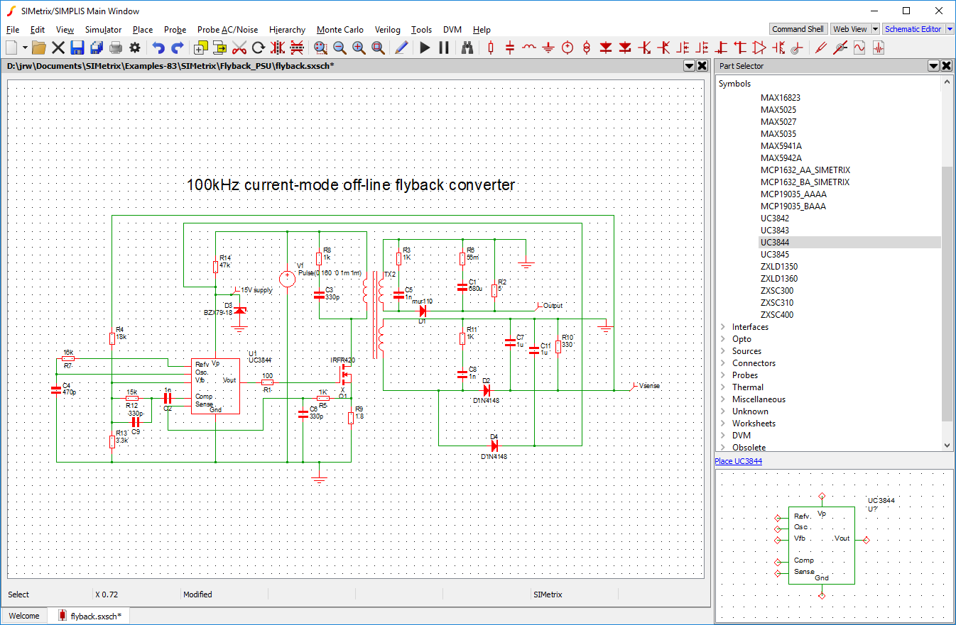
Schematic Editor Window
Editing Operations
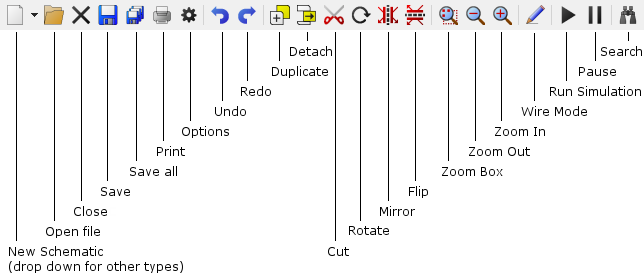
In the following notes references are made to the schematic tool bar. The diagram above shows the standard toolbar and the function of each button.
To Place a Part
Parts are most conveniently placed using the parts selector which is located on the right hand side of the schematic window. If it is not showing, select menu to make it visible. The part selector is a hierarchical categorised list containing nearly all parts available. When you find the part you want, click on it then either right click to see menu options or click on the Place link between the list and the symbol view.
If you cannot find what you are looking for select menu to open the SIMetrix search tool. You can also use the Search button: 
Some commonly used parts can be selected from the parts toolbar.
Once the symbol has been selected, using the mouse, move the image of the part to your desired location then press the left mouse button. This will fix the part to the schematic. Depending on preference settings (menu schematic tab), you may now be presented with another copy of the symbol for placement. Use left key as before to place, press right key to cancel.
You can rotate, mirror or flip the part before placing it on the schematic using the appropriate toolbar button or the keys F5, F6 or shift-F6 respectively.
If you place a two-terminal part directly over a wire, the wire will broken to allow the part to be connected in-line.
Selecting a Single Part
Most operations require items to be selected. When an item (part or wire) is selected, it changes colour to blue.
To select a single part, just left click it.
Selecting an Area
To select all items within a rectangular area of the schematic press the left mouse key in an empty area of the sheet and hold down while dragging mouse to opposite corner of rectangle. A rectangular box should be drawn as you move the mouse. (Note that if the initial cursor position is too close to a wire junction or part, a move operation will be carried out instead of selection.)
To Change Value or Device Type for a Part
First select it then select schematic popup Edit Part... or press F7. Alternatively, you can just double click the device. A dialog box appropriate for the type of part will be displayed. For devices requiring a model name, a list of available types will appear
To Rotate, Mirror or Flip a Part
Click the Rotate toolbar button or press key F5 to rotate a part.
This operation can be performed while a part is being placed or while a block is being moved or copied (see below).
You can also select a part or block then click the Rotate button or press the F5 key to rotate in situ.
To mirror a part or block through the y-axis, click the Mirror toolbar button or press the F6 key.
To flip a part or block (mirror about x-axis), click the Flip toolbar button or press shift-F6.
Wiring
See Wiring.
Deleting Wires
Select the wire by placing cursor over it clicking left button. Click the Cut toolbar button or press delete key.
Disconnecting Wires
Press the shift key, then select area enclosing the wire or wires to be deleted. Press delete button.
To Move a Single Part
Place the cursor within it and then drag it using the left mouse key. You can rotate/flip/mirror the part (see above) while doing so.
To Move More Than One Item
Select items as described above. Place cursor within any of the selected items then drag the items to the desired location. You can rotate/flip/mirror the items (see above) while doing so.
To Move Items Disconnected
Select items as described above then click the Detach toolbar button. Move items to desired location then press left mouse key. You can rotate/flip/mirror the items (see above) while doing so.
To Move Property Text (Labels)
SIMetrix provides the ability to move property labels simply by dragging them with the mouse but this method is disabled by default. To enable, use menu then in Schematic sheet select Enable GUI property edits in the Property editing box.
Although this is of course a convenient method for moving property labels, our recommendation is that this method is kept switched off. Our philosophy is that it is better to move the symbol so that the label is clearly visible rather than move the label itself. See Notes on Property Text Position for a discussion.
You can also move a part's value, by pressing ctrl-F7 and its reference using ctrl-F8. To move any other property select device then popup .
To Duplicate Items
Select items as described above then click the Duplicate toolbar button. Move the items to your desired location then press left key to fix. You can rotate/flip/mirror the items (see above) while doing so.
To Copy Across Schematics
Select block you wish to copy. Choose menu . In second schematic choose .
To Delete
Select items as described above then click the Cut toolbar button or press the delete key.
Multiple Selection
Individual items which do not lie within a single rectangle can be selected by holding down the control key while using the mouse to select the desired items as described above.
Selecting Wires Only
Hold down shift key while performing select operation.
Holding Down the ALT Key...
Unselecting
Place the cursor in an empty area and press left mouse key.
Unselect Items Within a Rectangle
You can unselect an area of schematic enclosed by the selection box. Use menu .
To Change a Part Reference
Select part(s) then press F8 or select schematic menu . Enter new reference.
To Correct a Mistake
Click the Undo toolbar button. By default you can backtrack up to ten operations (but this can be changed with ). If you want to undo the undo operation, select the menu menu item.
To Add Text To a Schematic
Select the popup menu item . This opens a dialog box prompting you for the text to be entered. After entering text and closing box you can then position the text where you require using the mouse.
To Change Text Already Entered
Select the text then press F7 and enter the new text.
To Hide A Part Value
Select popup menu item Hide/Show Value
To Disable/Enable a Schematic Part
Schematic parts may be disabled so that, for simulation purposes, they behave as if they are not present on the schematic.
To disable one or more parts, first select them then select right click menu Disable selected. Each of the disabled parts will grey-out and show with a cross through it.
To re-enable, select then right click menu Enable selected.
Any part may be disabled, including regular components, probes, terminals, module ports, ground symbols and bus rippers. Be aware that if you use this method to disable an inline current probe, the probe will become an open circuit.
To Short-circuit a Schematic Part
Schematic parts may be short-circuited so that they appear as a wire connection for the purposes of simulation. This operation is similar to disabling in that the part is effectively removed from the circuit, but in addition one or more pairs of pins are connected.
To short-circuit one or more parts, first select them then select right click menu Disable & Short-circuit Selected. Each of the disabled parts will grey out and show with a thick line connecting one or more pairs of pins.
For two-terminal parts both pins are connected unconditionally. If the part has more than two pins, the connected pair or pairs is determined from the value of the SHORTPINS property. This property is in the form:
n1-n2[,n3-n4]...
Where n1, n2 etc are pin numbers starting from 1. This is the same as the pin-order as defined in the symbol editor.
For example "1-3" connects pin 1 to pin 3. "1-3,4-6" connects pin 1 to pin 3 and pin 4 to pin 6.
If the part has no SHORTPINS property, no action will be taken and an error message will be displayed in the command shell. Note that the SHORTPINS property will be read directly from the symbol definition if not present on the instance.
Breaking Wires
If you place a new two pin part onto the schematic and both pins of the part land on the same wire, thus shorting out the part, the wire will automatically be broken and so inserting the part in series.
This will also occur when copying, moving or duplicating existing parts as long as the part was not already short circuited before the operation was started.
The same action will occur for parts with more than two pins if a SHORTPINS property is defined for the part. SHORTPINS is described above To Short-circuit a Schematic Part.
Zoom Area
Click the Zoom box toolbar button then drag mouse to zoom in on selected area.
Zoom Full (Fit to Area)
Select popup or press HOME key to fit whole schematic in current window size.
Zoom Out
Click the Zoom out toolbar button or press F12 to zoom out one level.
You may also zoom out by holding down the control key and rolling the mouse scroll wheel backwards
Zoom In
Click the Zoom in toolbar button or shift-F12 to zoom in one level.
You may also zoom out by holding down the control key and rolling the mouse scroll wheel forwards
Panning
The easiest way to pan the schematic is with the mouse scroll wheel. Just rotate the wheel for vertical pan. For horizontal pan, hold down the shift key and rotate the wheel.
You may also use the scroll bars, cursor keys and page up and down keys to pan schematic. The left, right, up and down cursor keys pan the schematic one grid square in the relevant direction and the Page up, Page down, control left cursor, control right cursor to pan the schematic 10 grid squares.
Notes on Property Text Position
The SIMetrix schematic editor has been designed using a basic principle that it is better to move the part to make its property text visible rather than move the property. That way the part's value and other properties will always have a consistent location relative to the symbol body and there will be no confusion as to which part it belongs.
If you have a situation where some device label (=property text) clashes with another, your first thought will probably be to move the label. We ask you instead to think about moving the part that owns the label; it's nearly always a better way. In situations where the label is very long, it might be better to hide it altogether.
If you find that moving the label is the only way then you should be aware of how the positions of property text are defined.
In SIMetrix, property positions can be defined in one of two ways namely Auto and Absolute. Most of the standard symbols have their properties defined as Auto. This means that SIMetrix chooses the location of the property on a specified edge of the symbol and ensures that it doesn't clash with other properties on the same edge. Auto properties are always horizontal and therefore easily readable. The position of Absolute properties is fixed relative to the symbol body regardless of the orientation of the symbol and location of other properties. When the symbol is rotated through 90 degrees, absolute text will also rotate. Absolute properties are intended for situations where the precise location is important, such as in a title block.
When a visible property on a symbol is moved by the method described above, it and all other visible properties on that symbol are converted to Absolute locations. This is the only way that the positions of all properties can be preserved. This means that once you move a single property on a part, it and all other properties will rotate with the symbol. For this reason, it is better not to move property text until the orientation of the symbol has been finalised.
Wiring
Overview
SIMetrix offers both manual and smart wiring methods. In smart mode, you select the start and end points and SIMetrix will find a suitable route. In manual mode, you place each wire segment individually in exactly the locations you require. You don't need to change global settings to select the mode you desire; the procedures for each mode are different and so you can freely switch between them from one wiring operation to the next.
However, in most applications you won't need to use the manual wiring method. The smart wiring method can still be used to enter wire segments one by one, simply by selecting start and end points that have an obvious straight line route. The fundamental difference between smart and manual is that smart mode will always route around obstacles such as existing wire terminations or whole symbols. In manual mode the wire will always go exactly where you take it even if it crosses existing connections or passes through existing symbols.
Smart Wiring Procedure
- Initiate smart wiring by bringing the mouse cursor close to either an unselected symbol pin or an unselected wire end. As you do this you will notice that the cursor changes shape to depict a pen symbol.
- Click the left button (press and release), to mark the starting point of the wire connection.
- Move, the cursor to the destination point. This may be anywhere on the schematic, not just at a wire end or symbol pin.
Smart Wiring Notes
The smart wiring algorithm use an heuristic algorithm that finds as many routes as possible then chooses the best one based on a number of criteria. The criteria used in the selection include the number of corners, the number of wires crossed, the number of property labels crossed and its overall length. It attempts to find the most aesthetically pleasing route, but as this is somewhat subjective, it may not necessarily find the route you may have chosen manually. However, in our tests, we have found that it usually finds the best route for situations where there are no more than 2 or 3 corners required. In developing the algorithm we paid particular attention to common scenarios found in analog design such as routing the output of an opamp back to its inverting input and you should find that these common scenarios work well.
Smart Wiring Options
There is two option to control the smart wiring algorithm. Firstly, you can disable the smart wiring algorithm altogether, in which case the smart wiring procedure will place wires in a similar fashion to the manual wiring methods.
Secondly, there is an option that controls whether or not the smart wiring algorithm is allowed to route wires through existing wires that are connected to the start and end points. By default this option is on, i.e. the smart algorithm is allowed to route through connected wires. If the option is off, the algorithm will not allow any wires in the route to connect to any existing wire regardless of what it is connected to. In general, we recommend that the option is left switched.
To change the smart wiring options, select menu . The two wiring options are in the section titled Wiring.
Manual Wiring Procedure
If you have a three button mouse you can start a wire by clicking the middle button. Clicking the middle button a second time will complete the wire and start a new one. Click the right button to terminate wiring.
If you have a two button mouse you can start a wire by pressing F3 or double clicking the left button. Single clicking the left button will complete the wire and start a new one. Click the right button to terminate wiring.
Alternatively, click the Wire button on the toolbar. You can start a wire by single clicking the left button, otherwise continue as described above. Press the Wire button again to cancel this mode.
Bus Connections
SIMetrix provides the Bus Ripper symbol to allow the connection of buses.
To Add a Bus Connector
-
Select the menu
This will display dialog:
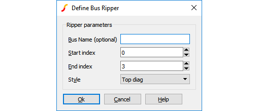 Enter a bus name if you require it.
- Start index and end index define the wires within the bus that you wish to connect to. Suppose you were connecting to a data bus called DATA and it was 16 bits wide. If you wish to make a connection to the 4 bits from DATA8 to DATA11, you would enter 8 and 11 for the start and end index respectively. The bus ripper doesn't care about the size of the bus to which it is connecting.
- Choose an appropriate style. This only affects the appearance of the symbol not its functionality.
- Click Ok then place the symbol on your schematic.
To Draw Buses
There is no special method of drawing buses. Simply wire up bus rippers as you would any other part. As soon as you connect to the bus pin of a bus ripper, the colour and thickness of the wire will automatically change to signify that it is a bus.
To Increase/Reduce the Connections to a Bus
If you wish to add connections to or delete connections from a bus ripper, select the ripper device and press F7 or popup menu Edit Part.... The same dialog as above will be displayed. Adjust the start and end indexes appropriately then close the box.
Connecting Buses in a Hierarchy
Copying to the Clipboard
To copy schematics to the clipboard, select the entire schematic then choose menu . If you wish the schematic to be copied in black white select . It is recommended that you zoom the schematic to fill the window prior to copying to the clipboard.
After copying to the clipboard, the schematic can be pasted into another application such as a word processor.
Annotating a Schematic
You can add a caption or free text to a schematic. The only difference between them is the font style and justification. Captions use a heavy font and are centre justified. Free text use a smaller font and are left justified. To place a caption or free text use the popup or fixed menus:
Assigning Part References
Standard Behaviour
As you place parts on a schematic, they are automatically assigned a part reference (R1, Q42, C11 - etc.). These references are assigned in sequence and breaks in the sequence are reused. So if you place resistors on the schematic R1, R2, R3 and R4 then delete R2, the next resistor placed will use the reference R2 that has become available.
Setting Start Value
By default, auto assigned references start at 1. You can change this using the AnnoMinSuffix option variable (see the table in List of Options). For example, type this at the command line:
Set AnnoMinSuffix=100
Auto assigned part references will now begin with 100.
Assigning By Position
You can reassign part references so that they are allocated by their position on the schematic. To do this select menu .
Checking the Schematic
The schematic menu performs a number of checks. First, a netlist of the circuit is created. During this process the following potential errors will be reported.
- Unconnected pins.
- Dangling wires.
- Implicit connections (e.g. two terminal symbols with the same name)
- Name translations. This is for buses with different names connected together. One name has to win.
- Shorted parts. Any parts with two or more pins which have all their pins connected to each other.
Schematic Preferences
Part Toolbar
The default toolbar show a selection of symbols useful. There are however many more buttons available and these can be added as desired. To do this select the schematic menu . This will display a dialog box allowing full customisation of the part buttons on the schematic toolbar. Note that the toolbar configuration in SIMetrix mode is independent of the configuration in SIMPLIS mode.
Further customisation of all toolbars is possible using script commands. You can also define your own toolbars and buttons. Full details may be found in the Script Reference Manual
Part Placement Options
You can specify whether or not you prefer multiple or single placement of parts. By default, placement of parts from the schematic tool bar is repetitive while placement of parts from the menus is done one at a time. This can be changed. Select the menu . In the schematic sheet, the options available are presented in the Placement box.
Adding and Removing Worksheets
A number of standard sizes of worksheet are included. See menu . The worksheet menus automatically protect the worksheet after it has been placed. This prevents it from being selected. To delete a worksheet, use the menu. You should avoid placing a worksheet from the menu as it will not be protected if you do this.
Finding and Specifying Net Names
When a simulation is run, a netlist of the schematic is created and this is delivered to the simulator. The netlist generator automatically assigns names to every net (or node) of the circuit. There are some situations where you need to find the name of a net. For example, in noise analysis (see Noise Analysis) you must specify an output node. In these situations you can either find the name of the net that the netlist generator assigned or alternatively you can specify a name of your choice.
To Find an Assigned Net Name
Place the mouse cursor on the net of interest. You will see the name appear in the fifth entry of the status box at the base of the schematic window in the form "NET=netname". Note that the schematic must have been netlisted for this to work. Netlisting occurs when you run a simulation for example, but you can force this at any time by selecting the menu .
To Specify a User Defined Name
User defined net names can be specified using either the Terminal symbol or the Small Terminal symbol. Select menu or . To specify the net name select the terminal then press F7 and enter your choice of name.
| ◄ Interface Styles | Hierarchical Schematic Entry ▶ |