5.1 Passing Parameters into Subcircuits Using the SIMPLIS_TEMPLATE Property
In this topic you will learn how the SIMPLIS_TEMPLATE property defines the symbol-to-subcircuit interface and allows you to pass parameters from the symbol to the subcircuit. The symbol can be designed to use either the single property or multi-property method, this topic focuses on the multi-property method which is also the preferred method. The single property method is described in the Appendix 5.B - Single Property Parameterization topic.
To download the examples for Module 5, click Module_5_Examples.zip.
In this topic:
Key Concepts
This topic addresses the following key concepts:
- Parameters are passed to subcircuits on the SIMPLIS_TEMPLATE property.
- The multi-property method stores each parameter on an individual symbol property.
What You Will Learn
In this topic, you will learn the following:
- How to store parameters on the symbol using symbol properties and the multi-property method.
- How to use the SIMPLIS_TEMPLATE property, which defines the symbol-to-subcircuit interface, to pass parameters into subcircuits
Getting Started
In this topic, you will learn the multi-property method for parameterizing a subcircuit symbol. The multi-property method passes symbol properties through the symbol-to-subcircuit interface where the symbol property values are used as model parameters. In general, the multi-property method is the recommended method; however, in some circumstances, the single-property method is a better choice. For more information, see the Appendix 5.B - Single Property Parameterization topic.
In addition to using the SIMPLIS_TEMPLATE property, you can pass parameters into a subcircuit using the special PARAMS property. While this is not the preferred method, a number of symbols exist which use this method. Using the PARAMS property is covered in the Appendix - Passing Parameters into Subcircuits Using the PARAMS Property topic.
For the rest of Module 5, a single-pole filter is used as an example. The single pole filter uses three parameters to configure the filter:
| Parameter | Default Value | Description |
| FC | 10k | The filter pole frequency in Hertz |
| R_VAR | 1k | The resistor value used in the R-C filter in Ωs |
| GAIN | 1 | The gain of the filter in V/V |
Multi-Property Method
The multi-property method uses a dedicated symbol property for each parameter. This has the advantage that each symbol property can be displayed on the schematic or hidden from view. In the next exercise, you will add properties using the multi-property method.
Exercise #1: Parameterize Using the Multi-Property Method
In this exercise, you will use the symbol editor to add a symbol property for each parameter. Although it is not strictly necessary, you will use the parameter name for the symbol property name. For example, the FC parameter will be saved on a symbol property named FC.
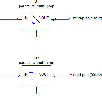
- Open the schematic 5.4_parametrized_rc_filters_multi_prop.sxsch.
- Select U2.
- Right click to bring up the context menu, and then select Edit Symbol...to edit the symbol for the schematic component param_rc_multi_prop.sxcmp.
- To add a symbol property for each name in the following table, follow the steps
below:
Symbol Property Name Symbol Property Value FC 10k R_VAR 1k GAIN 1 - From the Symbol Editor menu, select , and then add a symbol property with the name and value from the table above.
- To display the symbol property between the name of the schematic component and the symbol, select Auto Normal = Top in Text Location group.
- Check the Show name and Selectable check boxes. Result: The configured dialog for the FC parameter is shown below:
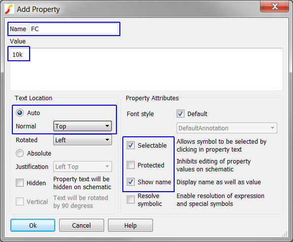
- Click Ok to save the symbol property.
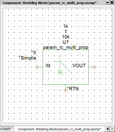
- Repeat steps a through d for the R_VAR and GAIN symbol
properties. Result: The symbol with the added properties appears as follows:
- To add the SIMPLIS_TEMPLATE property to pass the symbol properties
FC, R_VAR, and GAIN through the symbol-to-subcircuit
interface, follow these steps:
- From the Symbol Editor menu, select .
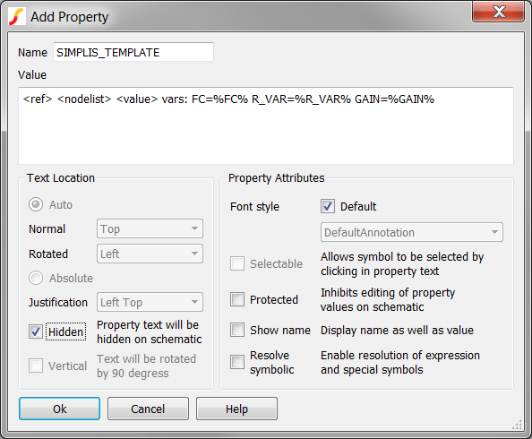
- Type SIMPLIS_TEMPLATE in the Name field, and add the following in the Value field: <ref> <nodelist> <value> vars: FC=%FC% R_VAR=%R_VAR% GAIN=%GAIN%
- In the Text Location group, select Auto Normal = Top for the symbol property.
- Check the Hidden check box on the Add Property Dialog. Result: The configured SIMPLIS_TEMPLATE add property dialog should appear as follows:
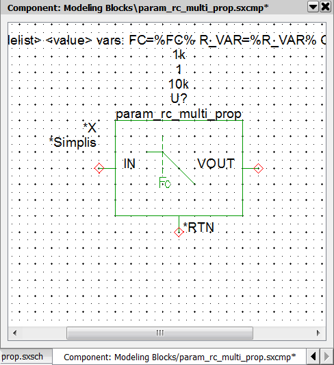
- Click Ok to add the SIMPLIS_TEMPLATE property. Result: You have now configured the symbol to use the multi-property method. The symbol editor should appear as follows:
- Press Ctrl+S to save the symbol.
- Click Ok on the Save Symbol dialog to save the symbol to the component file, and then close the Symbol Editor window.
- To update the instantiated symbols on the schematic, follow these steps:
- Select U1.
- Press and hold the Ctrl key while selecting U2. Result: Both symbols for U1 and U2 are selected:
- Right click to bring up the context menu and select Restore
Properties...
Result: A dialog opens, for you to confirm that you want to add the new properties to the instantiated symbols:
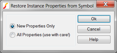
- Click Ok. Result: The schematic instances for U1 and U2 are updated with the new symbol properties:
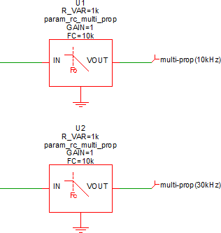
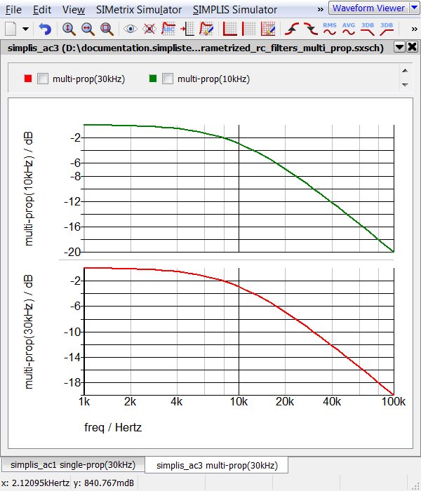
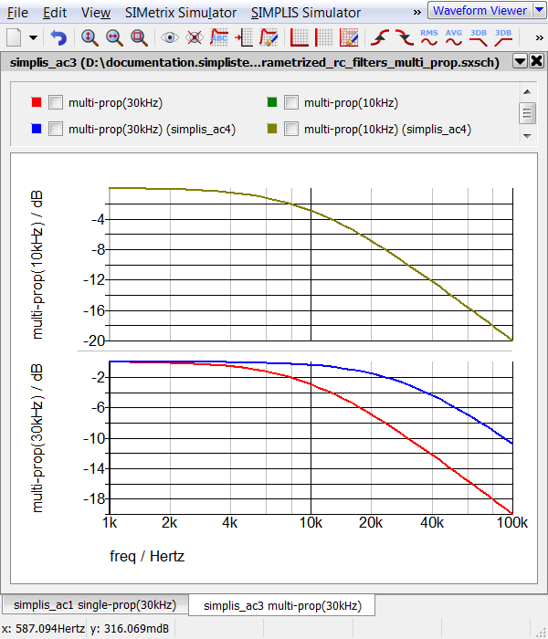
- Press F9 to run the simulation. Result: The design simulates in SIMPLIS and two gain curves are output, one for each of the two filters. The pole frequency is 10kHz for both filters as the passed parameters are identical for both U1 and U2.
- Double-click on the FC property for U2, this will open the Edit Property
dialog. Change the FC value to 30kHz. The Edit Property dialog should
appear as follows:
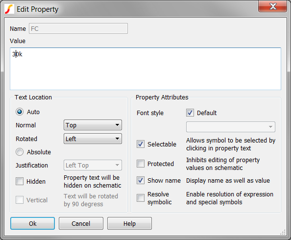
- Click Ok on the Edit Property dialog and run the simulation.Result: The blue output curve for the 30kHz filter now reflects the change to the FC parameter.
Discussion: Exercise #1
You can now double click on any of the symbol properties to edit the individual symbol properties. Since each symbol property is passed as a model parameter, you are directly editing the model parameters. This is one of the main advantages to the multi-property method. You can also choose which parameters to show and which to hide.
Conclusions and Key Points to Remember
- The SIMPLIS_TEMPLATE symbol property defines the netlist entry; therefore, parameters are passed through the symbol-to-subcircuit interface with the SIMPLIS_TEMPLATE.
- Symbol property values can be literally substituted into the SIMPLIS_TEMPLATE by
enclosing the property names with the percent symbol on the SIMPLIS_TEMPLATE property
value. For example %FC% is replaced with the value of the symbol property
FC. Note: This substitution is used only on the TEMPLATE and SIMPLIS_TEMPLATE properties.