PFC POP Trigger Schematic Device
The SIMPLIS Periodic Operating Point (POP) analysis, and therefore also the SIMPLIS AC analysis which can only be run once POP analysis completes successfully, requires the user to designate a switching node which is the least common multiple of the period frequencies present in the circuit. The user designates such a node by connecting it to the input of POP Trigger Schematic Device. In a power factor correction (PFC) rectifier circuit, there are at least two periodic frequencies: the line frequency of the AC input voltage to the PFC rectifier, and the switching frequency of the PFC rectifier. The logical approach would be to connect the POP Trigger Schematic Device to the AC line. However, unless the switching frequency is exactly an integer multiple of the line frequency, POP analysis will not succeed. More precisely, unless there is an exact integer number of conversion cycles in one AC line cycle, the POP analysis will not succeed.
In many PFC rectifier circuits, whether with constant or variable switching frequency, the switching frequency is indeed not an integer multiple of the line frequency, causing POP analysis to fail. The PFC POP Trigger Schematic Device allows the user to synchronize the AC line and PFC rectifier switching frequency, by making (ideally) barely perceptible changes to the switching frequency, so that the switching frequency becomes and exact integer multiple of the line frequency. This then allows a POP and AC analysis to be run successfully.
In this topic:
| Model Name: | PFC POP Trigger Schematic Device | |
| Version Available: | 9.1d+ | |
| Simulator: | This device is compatible with the SIMPLIS simulator | |
| Parts Selector Menu Location: | TBD | |
| Symbol Library: | simplis.sxslb | |
| Model File: | simplis_param.lb | |
| Symbol Name: | PFC_POP_TRIGGER_v1 | |
| Subcircuit Name: | PFC_POP_TRIGGER_v1 | |
| Symbol: | 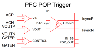
|
|
| Multiple Selections: | Only one PFC POP Trigger device is permitted on a schematic. | |
Placing the PFC POP Trigger Schematic Device
The PFC POP Trigger Schematic Device has embedded inside of it a regular POP Trigger Schematic Device. As only one POP Trigger is permitted per schematic, this means that only one PFC POP Trigger is permitted per schematic as well. Also, this means that it is not allowed to place both a PFC POP Trigger and a regular POP Trigger on a schematic.
Connecting the PFC POP Trigger to the PFC rectifier circuit is more complex than connecting just a regular POP Trigger. Unlike with the regular POP Trigger where only the input is connected to the circuit, the PFC POP Trigger outputs a synchronization current which must also be connected to the PFC rectifier circuit. This synchronization current is what synchronizes the switching frequency with the line frequency. To which node the of the PFC rectifier circuit the synchronization current of the PFC POP Trigger should be connected to is highly dependent on the type of PFC rectifier circuit being simulated. For example, in a critical conduction mode (CCM) PFC rectifier where the switching frequency is variable and depends on the load, the PFC POP Trigger synchronization current should be connected in parallel with the load current of the PFC rectifier. On the other hand, in a constant frequency mode (CFM) PFC rectifier, the PFC POP Trigger synchronization current should be connected to a node in the controller which generates the switching frequency (e.g. a part of the oscillator). The description of the pins of the PFC POP Trigger Schematic Device and which nodes of the circuit they should be connected to is given in the table below.
| Pin Name | Description |
| ACP | Connect this pin to the positive node of the AC input line. |
| ACN | Connect this pin to the negative node of the AC input line. The voltage between ACP and ACN should be equal to the AC line input voltage. |
| VOUTP | Connect this pin to the positive node of the PFC rectifier output voltage. |
| VOUTN | Connect this pin to the negative node of the PFC rectifier output voltage. The voltage between VOUTP and VOUTN should be equal to the PFC rectifier output voltage. |
| GATEP | Connect this pin to the positive node of the gate signal for switch (e.g. MOSFET) of the PFC rectifier. |
| GATEN | Connect this pin to the negative node of the gate signal for the switch of the PFC rectifier. If such a node is not available, connect this pin to ground. The voltage between GATEP and GATEN should be equal to the gate signal voltage of the switch. |
| IsyncP | This pin is the positive node of the PFC POP Trigger synchronization current, which flows from IOUTP to IOUTN. Connect this pin to the positive node of the circuit which determines or directly affects the switching frequency of the PFC. This will vary based on the details of the PFC rectifier schematic. E.g., in a CCM PFC rectifier schematic, connect this pin to the positive node of the output current; in a CFM PFC rectifier circuit where a capacitor-based oscillator is used to generate the switching frequency, connect this node to the positive node of the oscillator capacitor; in a CCM PFC where a voltage-controlled oscillator (VCO) is used to generate the switching frequency, connect this pin to the positive node of a resistor or current-controlled voltage source which is turn connected to the VCO input; etc. |
| IsyncN | This pin is the negative node of the PFC POP Trigger synchronization current, which flows from IOUTP to IOUTN. Connect this pin to the negative node of the circuit which determines or directly affects the switching frequency of the PFC. This will vary based on the details of the PFC rectifier schematic. E.g., in a CCM PFC rectifier schematic, connect this pin to the negative node of the output current; in a CFM PFC rectifier circuit where a capacitor-based oscillator is used to generate the switching frequency, connect this node to the negative node of the oscillator capacitor; in a CCM PFC where a voltage-controlled oscillator (VCO) is used to generate the switching frequency, connect this pin to the negative node of a resistor or current-controlled voltage source which is turn connected to the VCO input; etc. Often, this negative node will be the ground node. |
| IN_SS | This pin does not have to be connected to any other node in the schematic. The voltage on this pin goes high when the PFC POP Trigger determines during a transient analysis that the line and switching frequency are synchronized and that the PFC rectifier is in steady-state. |
| POP_OUT | This pin does not have to be connected to any other node in the schematic. The voltage of this pin is the output of the PFC POP Trigger’s embedded POP Trigger during a POP analysis. |
Using the PFC POP Trigger Schematic Device
As noted earlier, the reason that a POP analysis will fail for many PFC rectifier circuits is that the switching and line frequency are not synchronized. For example, in a CCM PFC rectifier, at the operating point of interest there may be a non-integer number of switching cycles per line cycle (e.g., 3520.7 or 3521.3 instead of exactly 3521). In this case, the PFC POP Trigger will increase or decrease slightly the output load of the CCM PFC rectifier (e.g., by a few µA) to ensure that there are always an integer number of switching cycles in every line cycle at that operating point. Alternatively, in e.g. a CFM PFC rectifier with an AC input at 50 Hz, the oscillator maybe producing a switching frequency of 99.967854 kHz instead of an exact 100 kHz. In this case, the PFC POP Trigger will adjust the input to the oscillator (maybe by as little as a few nA) to produce a switching frequency of exactly 100 kHz, synchronizing it with the line frequency.
- Characterization – this step is performed during the first phase of the
transient analysis. During this step, the PFC POP Trigger determines the
current gain required for the particular PFC rectifier circuit: that is,
by how much the switching frequency of the circuit changes for each incremental
change of the PFC POP Trigger synchronization current. Note: The user can specify a current gain manually and skip this step. How much the current gain varies across different operating points of a PFC rectifier circuit varies on the details of a particular implementation and control scheme. In many cases, a current gain determined at one operating point will be the same or at least suitable for use over many other operating points, allowing the characterization step to be skipped.
- Synchronization – this step is performed during the second phase of the transient analysis. During this step, the synchronization current of the PFC POP Trigger Schematic Device is adjusted step-by-step in a feedback loop to gradually synchronize the AC line and rectifier switching frequency. When synchronization is achieved, the output of the PFC POP Trigger will stabilize to a constant value – the frequency offset value.
- POP Analysis – at the end of the synchronization step, i.e. at the end of the transient analysis, the frequency offset value (and the current gain if characterization was also previously performed) will be automatically written to PFC POP Trigger symbol. Now the PFC POP Trigger Schematic Device is ready for POP (and AC) analysis. It is recommended that the user initially add a .include statement in the F11 window of the schematic including the .init file generated at the end of the characterization and synchronization transient. During POP Analysis, the PFC POP Trigger just outputs the constant frequency offset value, making sure that the circuit is synchronized. Its embedded POP Trigger is connected to the AC line, and POP analysis attempts to find a periodic operating point at the AC line frequency.
Therefore, the user must first run a transient analysis that is long enough to characterize and synchronize the PFC rectifier circuit. The length of the transient should be determined by monitoring the PFC POP Trigger synchronization current – the transient must run long enough for the synchronization current to stabilize. After that, the user can run a POP and AC analysis.
At the same operating point, POP and AC analyses can be simply re-run with the same frequency offset value without having to re-run the synchronization transient. In circuits with variable switching frequency, the frequency offset value will be different at different operating points due to the change in switching frequency, necessitating a synchronization transient for each operating point. In order to save time, it’s good practice to save the .init files and record the frequency offset values resulting from synchronization transient runs at different operating points. In this way the user can repeat POP analyses for different operating points without having to re-run synchronization transients.
Editing the PFC POP Trigger Schematic Device
It is important to specify the PFC POP Trigger parameter values correctly and properly. Not doing so will mean that synchronization will fail, and that subsequently POP and AC analyses cannot be run. Do not assume that the default values are adequate for all parameters.
To configure the PFC POP Trigger Schematic Device, follow these steps:
- Double-click the symbol on the schematic to open the editing dialog.
- Make the appropriate changes to the fields described in the table below the image.
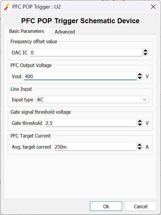
| Parameter Label | Units | Description |
| DAC IC | The frequency offset value as a unitless signed 32-bit integer, so as to be easily recordable without loss of precision. In conjunction with the current range parameter, it determines the initial condition of the PFC POP Trigger synchronization current. During a POP analysis, the PFC POP Trigger synchronization current is always held at this value. At the end of a transient analysis, the 32-bit signed integer value corresponding to the determined frequency offset current required to synchronize the circuit will be written to this parameter, overwriting any previous value entered by the user. | |
| Vout | V | The PFC rectifier circuit output voltage. |
| Input type | Select AC if the PFC rectifier circuit is connected to an AC input, to have the PFC POP Trigger behave as explained previously. If the PFC rectifier circuit is connected to a DC input, select DC, to have the PFC POP Trigger behave as simply a regular POP Trigger Schematic Device during a POP analysis. | |
| Gate threshold | V | The threshold of the low to high transition for the gate signal of the PFC rectifier switch. |
| Avg. target current | A | The average value of the current in the PFC rectifier circuit which determines the switching frequency, that is, to which the output of PFC POP Trigger is connected to. For a CCM PFC rectifier for example, this would be the average load current. Alternatively for a CFM PFC rectifier this might be the average current in the oscillator capacitor. |
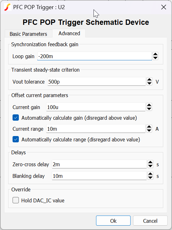
| Parameter Label | Units | Description |
| Loop gain | Determines the speed of the feedback loop that synchronizes the switching and line frequencies. The default value should be suitable for most circuits. | |
| Vout tolerance | V | The change is output voltage ripple from line cycle to line cycle at which the PFC POP Trigger will deem the circuit to be in steady state during a transient analysis. Does not affect the POP analysis in any way. |
| Current gain | A value specifying by how much the PFC target current changes for each incremental change in the PFC POP Trigger synchronization current. This value will vary greatly from circuit to circuit. If using the PFC POP Trigger with a circuit for the first time, it is highly recommended to check the box below and allow the PFC POP Trigger to characterize the circuit and automatically calculate the current gain. | |
| Automatically calculate gain | Check this box to disregard the value entered in the dialog for the current gain and calculate it automatically during the characterization step. If the box is checked, at the end of the transient automatically calculated gain will be written into the current gain parameter field above, overwriting any value previously entered by the user. | |
| Current range | A | Determines the range of the synchronization current of the PFC POP Trigger: from -0.5*current range to +0.5*current range. An appropriate current range is required for the PFC POP Trigger to have enough resolution in its synchronization current to successfully synchronize the system. The appropriate current range will vary across different PFC rectifier circuits. It is recommended to check the box below to automatically calculate the current range. |
| Automatically calculate range | Check this box to disregard the value entered in the dialog for the current range and automatically calculate the current range based on the PFC target current. | |
| Zero-cross delay | s | Determines how long after a zero-crossing of the AC line is the AC line period sampled. The default value should be appropriate for most circuits. |
| Blanking delay | s | The delay after which the PFC POP Trigger commences to characterize and synchronize the circuit during a transient analysis. Increase this value to e.g. activate the PFC POP Trigger only once the circuit has settled after start-up or a transient. |
| Hold DAC_IC value | Check this box to make the PFC POP Trigger output a constant current corresponding to the entered DAC IC value during an entire transient. This stops the PFC POP Trigger from synchronizing. Checking this box and setting DAC IC = 0 is equivalent to disabling the PFC POP Trigger. |