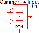
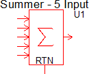
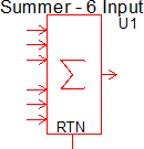
Summers (Version 8.0+)
The Summer models the addition or subtraction of up to six analog signals, each with their own gain. For example, using this model you could implement the mathematical expression:
\[ V_{OUT} = K_0 + K_1 \times V_1 + K_2 \times V_2 + K_3 \times V_3 + ... \]
where:
???MATH???K_1, K_2, K_3 ... ???MATH??? are the gain coefficients and
???MATH???V_1, V_2, V_3 ... ???MATH??? are the time dependent input signals.
Additionally, ???MATH???K_0???MATH??? is a constant offset which can be added to the output. The default value of ???MATH???K_0???MATH??? is zero.
The summer blocks are completely general purpose. The modeling techniques used in these blocks are optimized for both numerical accuracy and simulation speed.
In this topic:
| Model Name: | Summers (Version 8.0+) | ||||||
| Simulator: | 
|
This device is compatible with the SIMPLIS simulator. | |||||
| Parts Selector Menu Locations: |
|
||||||
| Symbol Library: | simplis_analog_functions.sxslb | ||||||
| Model File: | simplis_analog_functions.lb | ||||||
| Subcircuit Names: |
|
||||||
| Symbols: |
|
||||||
| Multiple Selections: | Multiple devices can be selected and edited simultaneously. | ||||||
Previous Version Compatibility
This symbol and editing dialog was introduced with version 8.0. While the model will simulate in versions prior to Version 8.0, the parameters will not be editable with the double click pop-up dialog.
For summers compatible with versions prior to version 8.0, see the parts selector entry:
These obsolete summer symbols use the same electrical model but with a different symbol and editing dialog.
Symbol Migration
Symbols placed on schematics in previous versions of SIMetrix/SIMPLIS can be automatically migrated to use the new symbols. The schematic tools menu will invoke a routine which migrates the existing symbols to the new symbols. As this action makes substantial changes to the schematic, it is recommended that you save a backup copy of the schematic first.
Editing the Summer
To configure the Summer, follow these steps:
- Double click the symbol on the schematic to open the editing dialog.
- Make the appropriate changes to the fields described in the table below the image.
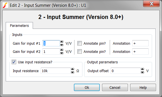
| Parameter Label | Units | Description |
| Gain for input #1 | V/V | The gain of the first input. The gain can be negative to implement the difference of two input signals. |
| Gain for input #2 | V/V | The gain of the second input. The gain can be negative to implement the difference of two input signals. |
| Annotate pin? | If Checked the pin will be annotated with the Annotation text. | |
| Annotation | The text describing this input | |
| Input resistance | Ω | The input resistance for all inputs |
| Output offset | V | The output voltage will be offset by this voltage |
Annotation
One of the new features added to the summers is the ability to add text annotation to the input pins. This annotation is purely for descriptive purposes and is not used in the electrical model. A simple example is a 2-input summer used to produce the difference between two signals. Adding "+" and "-" annotations to the pins will make the schematic easier to read.
Example
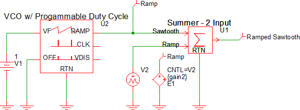
The test circuit used to generate the waveform examples in the next section can be downloaded here: simplis_075_simplis_summers.sxsch.
Waveforms
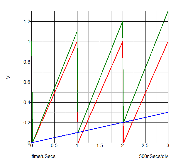
This example adds a high frequency oscillator sawtooth waveform to a slow moving ramp voltage. The sawtooth signal is red, the slow moving ramp is blue and the output is green.
