2.5 Change the Cooling Parameters in MDM
In this section of the tutorial you will modify the thermal properties of your inductor design in the Cooling tab of the main MDM window.
In this topic:
What You Will Learn
In this topic, you will learn the following:
- How to model the presence of a heat sink attached to one side of the inductor.
- How to model lower (or zero) thermal conduction from any side of the inductor.
2.5.1 Define a Different Thermal Environment for the Inductor
In a converter like the Buck converter used in this tutorial, natural convection is typically used to cool the converter. However, the inductor may be attached to a heat sink or other highly thermally conductive surface. At the same time, depending on how the converter is packaged, some sides of the inductor may not conduct very much heat at all. In the next procedure you will modify your inductor design with the RM4 core to reflect these changes in cooling parameters.
- Double-click the symbol L1.
- In the resulting dialog, click on Edit with SIMPLIS MDM...
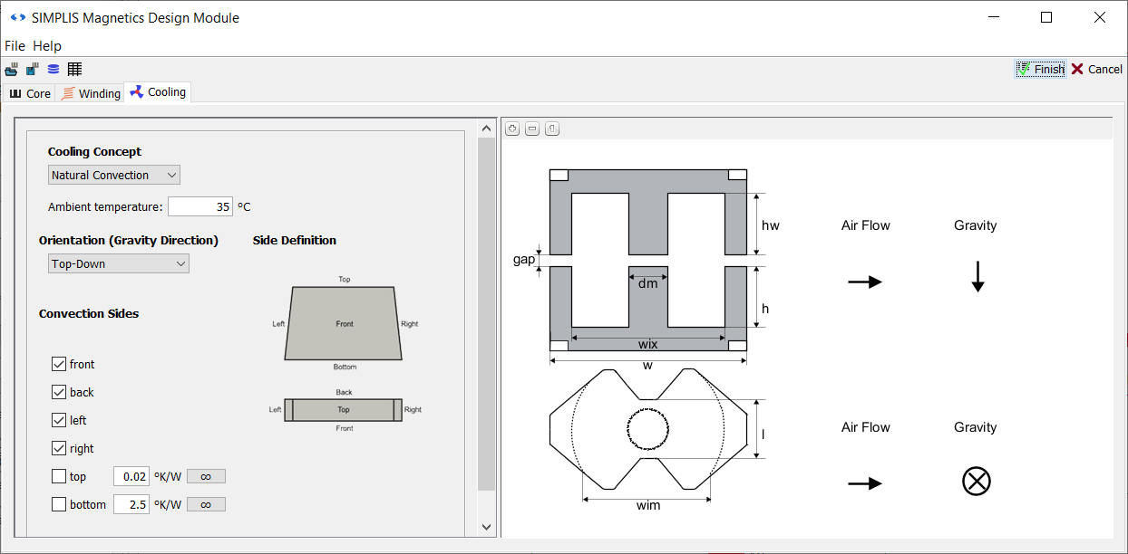
- In the main MDM window, go to the Cooling tab.
- Converters often operate at ambient temperatures higher than room temperature. To reflect this, change the Ambient temperature to 35.
- Uncheck the top checkbox under Convection Sides: and enter a thermal resistance of 0.02. This reflects that the top side is sitting against a thermally insulating material that will not conduct much heat away.
- Uncheck the bottom checkbox under Convection Sides: and enter a thermal
resistance of 2.5. This models the presence of a heat sink, with relatively higher
thermal conductivity, attached to the bottom side of the inductor. Result: The Cooling tab should now look like this:
- Click Finish.
Save the modified schematic as 2_my_buck_RM4_core_cooling.sxsch.
A complete schematic with the inductor design developed in this section, set up for MDM post-processing, is available as 2.5_SIMPLIS_MDM_tutorial_buck_converter_RM4core_heatsink.sxsch in the zip archive of schematic files.
2.5.2 Run the Simulation and Analyze the Results
Press F9 to run the simulation. Once MDM post-processing completes, the MDM results window will come up:
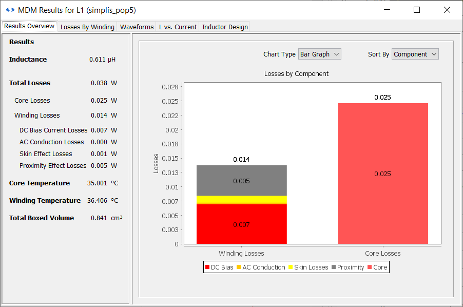
In the results from the previous section, 2.4 Refine the Inductor Design Using MDM, where only natural convection was applied to all sides, the inductor temperature was about 7 degrees above ambient.
Here, despite the fact that one side of the inductor is barely conducting heat, due to the presence of the heat sink the temperature rise is only one degree from ambient. So, the modified design is slightly cooler then the previous one despite operating in an ambient temperature that is 10 degrees hotter. This shows how thermal modeling can have a large impact on your results.
This completes the Buck converter inductor design portion of this tutorial. You can now close all the results windows and schematics that you worked with up to this point. In the next chapter, 3.0 PFC Inductor Considerations, you will briefly take a look at an inductor design for an AC/DC converter, a PFC, before moving on to transformer design in chapter 4.0 Flyback Converter Transformer Design.