4.1 Multi-Level Lossy Transformer
This section of the tutorial introduces the new Multi-Level Lossy Transformer SIMPLIS schematic symbol, available starting from version 8.40. Documentation for the transformer can be found here: Multi-Level Lossy Transformer (Version 8.4+).
In this topic:
Key Concepts
This topic addresses the following key concepts:
- Starting from version 8.40, you no longer need to manually construct your transformer model. You can use the Multi-Level Lossy Transformer.
- The different model levels represent transformer models with increasing complexity.
- Transformer model Levels 0-2 are defined directly by the user and do not require MDM to generate.
- In order to use SIMPLIS MDM to design a transformer, you must use the Level 3 model.
What You Will Learn
In this section, you will learn to the following:
- How to place a Multi-Level Lossy Transformer on your schematic.
- How to define the different models levels of the Multi-Level Lossy Transformer.
- The difference between the transformer model levels.
4.1.1 Place a Multi-Level Lossy Transformer on a Schematic
Create a new schematic by selecting from the menu bar. To place a multi-level lossy transformer,
- In the Part Selector go to Magnetics > Transformers.
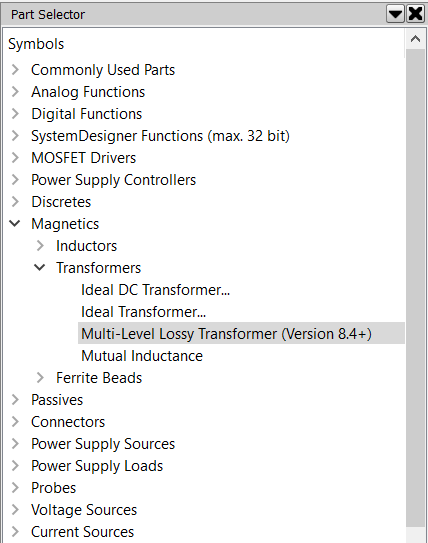
- Double-click on Multi-Level Lossy Transformer (Version 8.4+). Result: The Define Multi-Level Lossy Transformer dialog opens:
- Before you place the symbol, you must define the number of windings and the turns
ratio of the transformer. To do so, switch to the dialog's Windings tab:
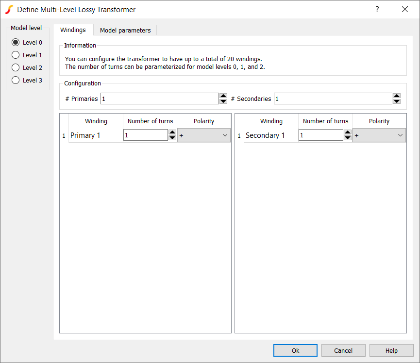
- For # Primaries enter 2.
- For # Secondaries enter 3.
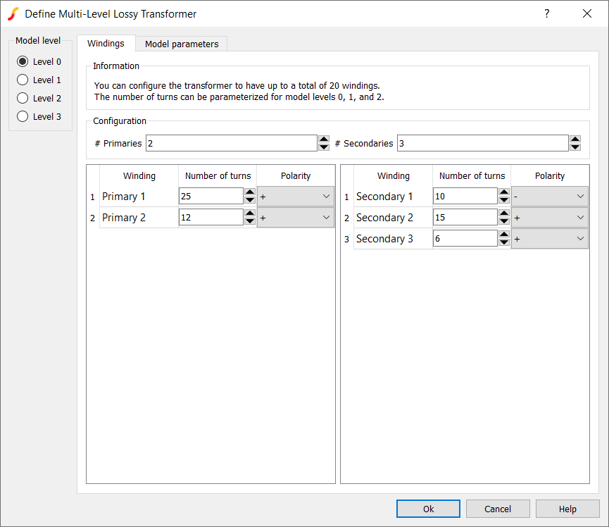
- For Primary 1, under Number of turns enter 25.
- For Primary 2, under Number of turns enter 12.
- For Secondary 1,
- Under Number of turns enter 10.
- Change the Polarity to -.
- For Secondary 2, under Number of turns enter 5.
- For Secondary 3, under Number of turns enter 6. Result: The dialog should now appear as follows:
- Click OK to close the dialog.
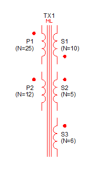
- Click on the schematic to place the symbol. Result: The two primaries, three secondaries transformer symbol is placed on the schematic. The first secondary winding has the dot on the bottom winding terminal, as defined in the dialog:
4.1.2 Transformer Model
There are four transformer model levels: 0, 1, 2, and 3.
Click on the Model level radio buttons to the left to examine the different model levels:
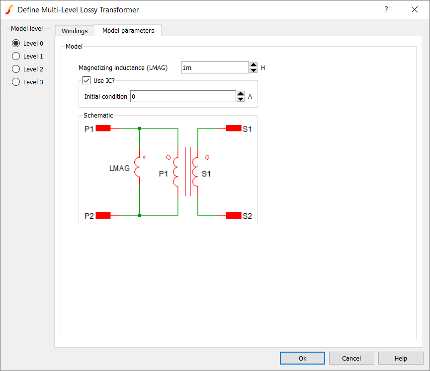
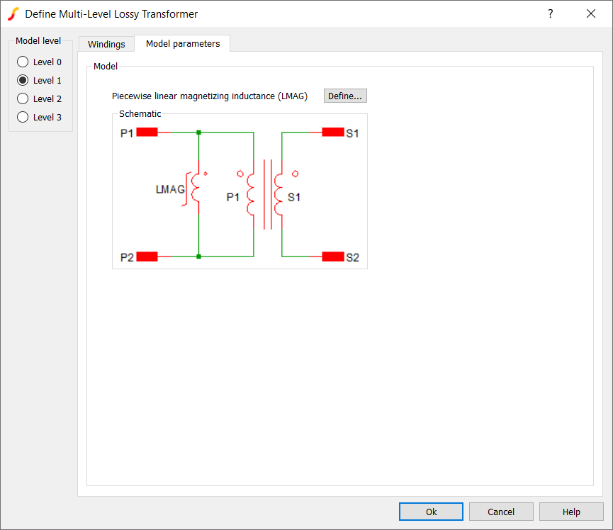
- The Level 0 model consists of an ideal DC transformer and a constant magnetizing inductance placed in parallel with Primary 1. To define a Level 0 model, just enter a value under Magnetizing inductance (LMAG).
- In the Level 1 model the magnetizing inductance becomes piecewise-linear
(PWL). To enter the PWL magnetizing inductance characteristic, click the
Define... button and enter a PWL inductance definition as a current vs.
flux linkage curve.
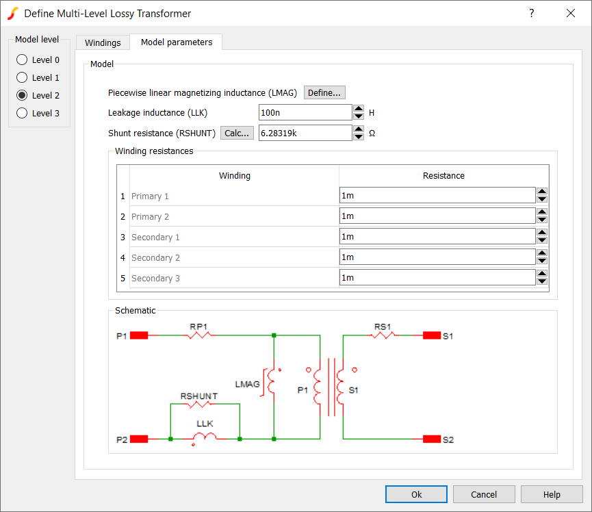
- The Level 2 model adds resistive loss by allowing you to define a constant resistance of each winding, and also adds a Leakage inductance (LLK) (also known as a stray inductance) in series with Primary 1, which
has a shunt resistance in parallel to it:
- The Level 3 must be created using SIMPLIS MDM:
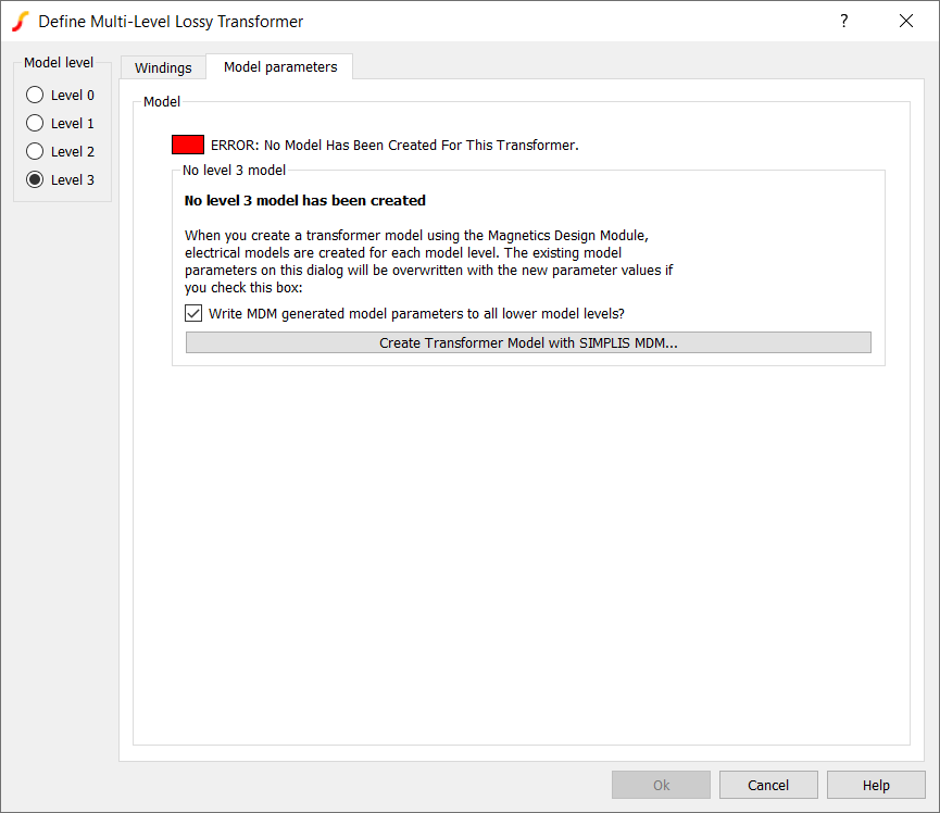
As you can see, the model status box for the Level 3 model is red, indicating that no SIMPLIS MDM model has been created for this transformer. The Write MDM generated model parameters to all lower model levels? is checked by default. This means that when you create a Level 3 model with MDM, the Level 0-2 models will be extracted from it, and all model levels will be consistent.
The models levels 0-2 are available to all users of SIMetrix/SIMPLIS. A license for SIMPLIS MDM is not required to use the Multi-Level Lossy Transformer with levels 0-2. All the parameters used in the level 0-2 models can be defined manually by the user. These model levels simply replace what you had to build manually in each schematic with separate ideal DC transformer, resistor, and inductor symbols prior to version 8.40.
Level 3 Model
It is important to note that unlike with the inductor in the previous sections, the Level 3 model generated by MDM is NOT structurally identical with the next-lowest (Level 2) model that can be defined manually by the user.
The Level 3 model is a reluctance model i.e. a magnetic circuit. This tutorial will not explain reluctance modeling in depth, but in short, in a magnetic circuit:
- Magnetic reluctance is analogous to electrical resistance.
- Magneto-motive force (MMF) is analogous to voltage.
- Magnetic flux is analogous to current.
Therefore, a magnetic circuit can be simulated by SIMPLIS as part of the schematic. It allows for an accurate simulation of the magnetic flux in each part of the core of the transformer. The reluctance model is derived from the physical model of the transformer that you create in MDM. In contrast to the Level 2 model, in the Level 3 reluctance model:
- The magnetizing inductance is modeled by a PWL reluctance distributed throughout the circuit, not placed only in parallel to Primary 1.
- There is a leakage reluctance defined for each winding inside the magnetic circuit, instead of a single lumped leakage in series with Primary 1.
- The winding resistances represent only the DC winding resistance of each winding.
Therefore, when simulating with a Level 3 model, you can expect slightly different behaviour than when simulating with a Level 2 model, due to the different, and more accurate model structure.
Close the dialog by clicking Cancel and close this schematic without saving it. You will create a Level 3 transformer model in SIMPLIS MDM in the next section.