SIMPLIS Transient Analysis
To set up a transient analysis, follow these steps:
- From the menu bar, select
- Check Transient in the Select analysis section on the right side of the dialog box.
- Click the Transient tab, and then enter the values which are shown and explained
below.
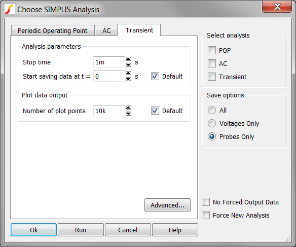
Parameter Description Stop time The finish time of a transient analysis. Start saving data at t = SIMPLIS starts saving plot data at this time. Number of Plot Points The total number of points to be generated. These points will be evenly spaced between the start and stop times. SIMPLIS automatically adds plot points whenever a PWL topology changes or a logic device changes state. For more information, see the Advanced SIMPLIS Training topic: 2.0.1 Transient Analysis Settings.
Advanced Options
The Advanced... button on the Transient tab of the Choose Analysis Dialog brings up the following dialog, allowing you to enable snapshot output and to specify an average topology duration.
Snapshot Output
SIMPLIS allows you to save its internal state in order to repeat a run where it had previously stopped. The internal saved states are known as snapshots. On the Transient Advanced Options dialog box, you can define the number of snapshots SIMPLIS creates and stores.
SIMPLIS always saves a snapshot at the beginning and end of each run. If you start a new run of the same circuit with the Start saving data at t = parameter equal to the stop time of the previous run, SIMPLIS does not need to rerun the simulation from time=0.
- If Force New Analysis is unchecked at the bottom right side of the Choose Analysis Dialog, SIMPLIS automatically loads the snapshot taken at the final time point of the previous simulation.
- If Force New Analysis is checked, SIMPLIS simulates from time=0 but ignores all data taken from previous simulations. Valid snapshots will not be loaded and SIMPLIS will simulate the circuit as if the circuit has never been simulated before.
The top section of Transient Advanced Options dialog allow you to specify the saving of snapshots at other times as well as the end of a run. This is useful if you want to restart a run at some before the end of the previous run.
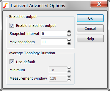
| Parameter | Description |
| Enable snapshot output | Check this box to enable saving of snapshot data. Snapshots are always saved at the beginning and end of a run. |
| Snapshot interval | Minimum time between snapshots |
| Max snapshots | Maximum number of snapshots that will be saved. This setting overrides Snapshot interval if there is a conflict. |
For more information how to apply snapshots, see the Advanced SIMPLIS Training: 2.0.1 Transient Analysis Settings.
Average Topology Duration
SIMPLIS calculates the average time it spends in each topology over a defined number of topologies. If this value falls below a minimum value the simulation aborts. The entries in the Average Topology Duration group define the parameters listed below.
| Parameter | Description |
| Minimum | If the average time falls below this threshold, the simulation will abort. |
| Measurement window | The number of topologies over which the topology duration is averaged. This uses a moving window averaging system. The purpose of this is to resolve problems with the simulation getting ‘stuck’ in situations with unexpected high-speed oscillations. If this happens you may wish to increase the minimum time or reduce the measurement window as appropriate. |
For more information about how to debug circuits which are run slowly or appear to be stuck at a simulation time, see the Advanced SIMPLIS Training: 4.5 Debugging Slow Simulations.
Early Start/Stop
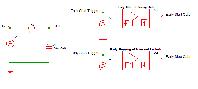
Starting in SIMetrix/SIMPIS V9.20, the SIMPLIS simulator supports the early start of saving simulation data for plotting and early stopping of the transient analysis. Such early actions are controlled by the logic output states of classic logic devices similar to the POP trigger device.
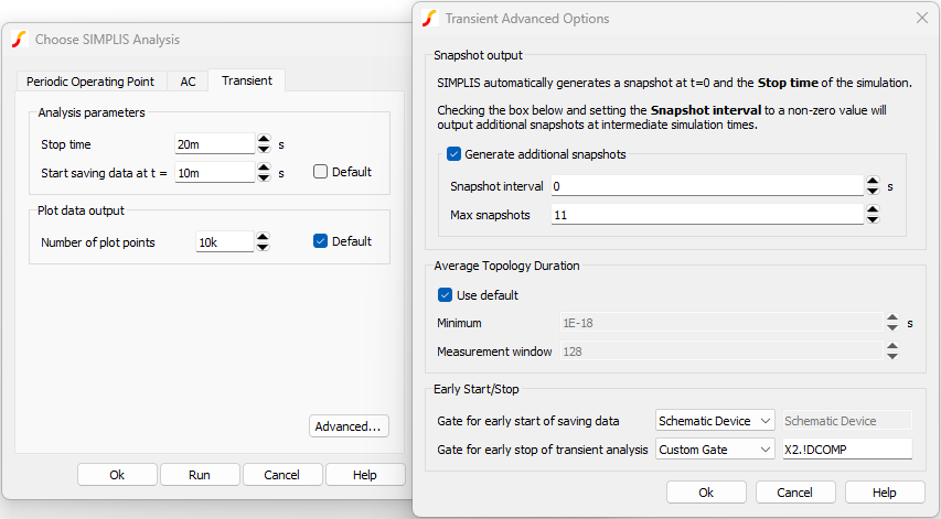
- The Gate for early start of saving data is defined in the Transient Advanced Options dialog, which is located in the Transient tab of the Choose SIMPLIS Analysis dialog.
- The output of the Gate for early start of saving data is equal to logic 1.
Hence, the Gate for early start of saving data should be set up so that its output state is at logic 0 at the beginning of the transient analysis and switch to logic 1 later when certain circuit conditions were met, indicating the preference to start saving data earlier than the time value set in the Start Saving Data at= window. Once the simulator has started to save data for plotting in the transient analysis, it will continue to do so until the transient analysis is stopped, even if the output of the Gate for early start of saving data has switched back to logic 0.
- The Gate for early stop of transient analysis is defined in the Trasient Advanced Options dialog, which is located in the Transient tab of the Choose SIMPLIS Analysis dialog.
- The output of the Gate for early stop of transient analysis is equal to logic 1.
Similar to the Gate for early start of saving data, the Gate for early stop of transient analysis should be set up so that its output state is at logic 0 at the beginning of the transient analysis and switch to logic 1 at some time later when certain circuit conditions were met, indicating there is no need for the continuation of the transient analysis.
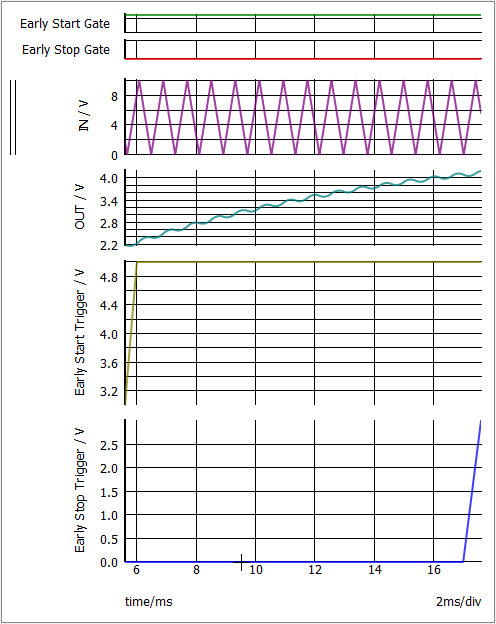
The Stop Time and Start Saving Data Time are set to 20 ms and 10 ms, respectively. The output of X1, the Gate for early start of saving data, switches to logic 1 at t=5.6 ms. As a result, the transient analysis starts saving simulation data for plotting at t=5.6 ms and not at t=10 ms as specified in the Start saving data at t= window. The output of X2, the Gate for early stop of transient analysis, switches to logic 1 at t=17.6 ms. As a result, the transient analysis is stopped at t=17.6 ms and not at the Stop Time of 20 ms.
- Disabled - functionality not active.
- Schematic Device - SIMPLIS will interrogate the schematic at run-time and search for special symbols*.
- Custom Gate - Manually define the full part reference of the output of a digital gate.
- If the parts selector is not shown, select from the menu bar.
- Click the arrow to open the Simulation Analysis Control Functions category.
- Select the desired device.
The Early Start of Saving Data and Early Stop of Transient Analysis features are totally independent of each other and they can be specified in any combination for a transient analysis.
Example
The following schematic, the Transient tab of the Choose SIMPLIS Analysis dialog, and the associated Trasient Advanced Options dialog illustrate how the SIMPLIS simulator can be instructed to start early in saving of plot data and stop early in the transient analysis. The example can be downloaded here, simplis_early_saving_data_and_early_stopping_analysis.sxsch.
At times, we may run a long transient analysis for a complicated circuit or a PFC circuit, looking for the behavior of the system when it is close to steady-state. While the POP analysis is normally the tool to use to converge to the periodic steady-state, there could be situations where the POP analysis may not be viable. For example, the POP analysis will perform well if the capacitors and inductors were given reasonable initial conditions. Yet, for a complicated circuit, it may be difficult to come up with reasonable initial conditions without knowing the periodic waveforms of the system. Hence, there is a need to run a long transient analysis, allowing the system to reach steady-state or close to steady-state in the simulation.
To run a long transient analysis, the Stop Time of the simulation is usually set to a sufficiently large value if we are not sure when the system will get close to steady-state. Take for example, the Stop Time may be set to 200 ms because we are not sure when the system would be close to steady state. To inspect the simulation data only for the last 10 ms, the Start saving data time will be set to 190 ms. But what if the system under simulation reaches steady-state much earlier at, say, 55 ms? By judiciously setting up the Gate for early start of saving data and Gate for early stop of transient analysis, we can allow the transient analysis to start producing simulation data for plotting when the system is close to steady-state at approximately 55 ms and stop at approximately 10 ms later. This could cut down the simulation time for the long transient analysis to play out all the way to 200 ms.