Statements Relating to POP Analysis
The statements relating to the Periodic Operating Point analysis can be all classified as control statements of the type defined in Chapter 6. An analysis statement to invoke the POP analysis and three option statements are associated with the Periodic Operating Point analysis.
In this topic:
.POP Statement for POP Analysis
The .POP statement instructs SIMPLIS to perform a Periodic Operating Point analysis on the system under study. Just like any other analysis statement, the .POP statement can only appear within the scope of definition of the main circuit. In addition, there can be no more than one .POP statement in an input file. The format for the .POP statement is
.POP  TRIG_GATE=gate_name TRIG_COND={0_TO_1|1_TO_0}
+ MAX_PERIOD=max_period
TD_RUN_AFTER_POP_FAILS=tran_after_pop_fail
where
| .POP | is the four-character keyword ".POP". |
| TRIG_GATE= | is the ten-character keyword "TRIG_GATE=". |
| gate_name | is the device name of a defined logic gate. This device is considered the triggering gate of the POP analysis. Together with the parameter value of TRIG_COND, it determines the condition that constitutes the start of a new switching cycle in the POP analysis. |
| TRIG_COND= | is the ten-character keyword "TRIG_COND=". |
| 0_TO_1 | is the six-character keyword "0_TO_1". |
| 1_TO_0 | is the six-character keyword "1_TO_0". |
| MAX_PERIOD= | is the eleven-character keyword "MAX_PERIOD=". |
| max_period | is a positive floating-point number assigned to the parameter MAX_PERIOD. |
| tran_after_pop_fail | Controls behaviour if the POP analysis fails to converge. This has three modes of operation as follows: tran_after_pop_fail = 0: Display error message then abort. tran_after_pop_fail = -1: Start a transient analysis with a run time equal to 100 x max_period (see above). tran_after_pop_fail = t, ???MATH???t>0???MATH???: Start a transient analysis with a run time equal to t. See Behaviour of POP Analysis after POP Convergence Failure for more details of this feature. |
Definition of the Start of A Switching Cycle
During a Periodic Operating Point analysis, SIMPLIS performs a sequence of time-domain transient analyses on the system. These transient analyses are invisible to the user. Each time-domain transient analysis is stopped when the operation of the system reaches the start of a new switching cycle. The user can define the condition constituting the start of a switching cycle through the TRIG_GATE and TRIG_COND parameters in the .POP statement. Let us examine the two .POP statements below:
.POP TRIG_GATE=!D1 TRIG_COND=0_TO_1 MAX_PERIOD=100U
.POP TRIG_GATE=X1.!D1 TRIG_COND=1_TO_0
+ MAX_PERIOD=100U
The first .POP statement defines the start of a switching cycle as the time instant when the output of the logic gate named !D1 switches from logic 0 to logic 1. The second .POP statement defines the triggering gate as the logic gate named !D1 in the subcircuit referred to as X1 in the main circuit, and it defines the start of a switching cycle as the instant when the output of the triggering gate switches from logic 1 to logic 0.
The two .POP statements above are shown here for illustration purposes. Only one .POP statement can appear in a SIMPLIS input file. The second .POP statement also demonstrates that the triggering gate is not restricted to the logic gates defined in the main circuit. It can be any logic gate defined in the input file.
Definition of the Start of A Switching Cycle for a Driven System
In a driven system, the driving periodic source is a good candidate to define the start of a switching cycle. Fig 10.1(a) shows a small section of a hypothetical circuit driven by a periodic triangular source V1 whose minimum and maximum voltages are, 1V and 3V, respectively. The triggering gate in this example is the comparator !D1 shown in the figure. Since V1 is periodic, the choice of the start of a cycle is arbitrary. For example, let us use the instant when the source value is decreasing and it is equal to 1.001V as the instant signifying the start of a switching cycle. The statements associated with the triangular source, the triggering gate, and the periodic operating point analysis for this example are:
V1 1 0 TRI V1=1 V2=3 FREQ=10K DRATIO=0.98
+ DELAY=0 OFF_UNTIL_DELAY=NO
!D1 5 0 1 2 M1 IC=0
.MODEL M1 COMP RIN=10MEG ROUT=8 HYSTWD= 2M
+ VOH=5 VOL=0
V2 2 0 DC 1.002
.POP TRIG_GATE=!D1 TRIG_COND=1_TO_0 MAX_PERIOD=300U
The model statement states that the output of the comparator is equal to logic 1 whenever the voltage at the non-inverting input is 1 mV above that of the inverting input, and that the output is equal to logic 0 whenever the voltage at the non-inverting input is 1 mv below that of the inverting input. Since the voltage at the inverting input of !D1 is a DC voltage source of 1.002 V, this implies that the output of !D1 is equal to logic 1 when the voltage of V1 exceeds 1.003 V, and it is equal to logic 0 when the voltage of V1 drops below 1.001 V. When the voltage of V1 is between 1.001 V and 1.003 V, the output state of !D1 remains unchanged. The diagram in fig 10.1(b) illustrates the relationship between the output state of !D1 and the voltage of source V1. The figure shows that the output of !D1 will have a logic 1 to logic 0 transition whenever the voltage of V1 is decreasing and equal to 1.001 V.
If there are multiple periodic sources driving the system, the periodic operating point analysis tool can be applied only if these sources are commensurate in their periods. In this case, the switching cycle should be defined with a period equal to the least common multiple of the periods of all periodic sources.
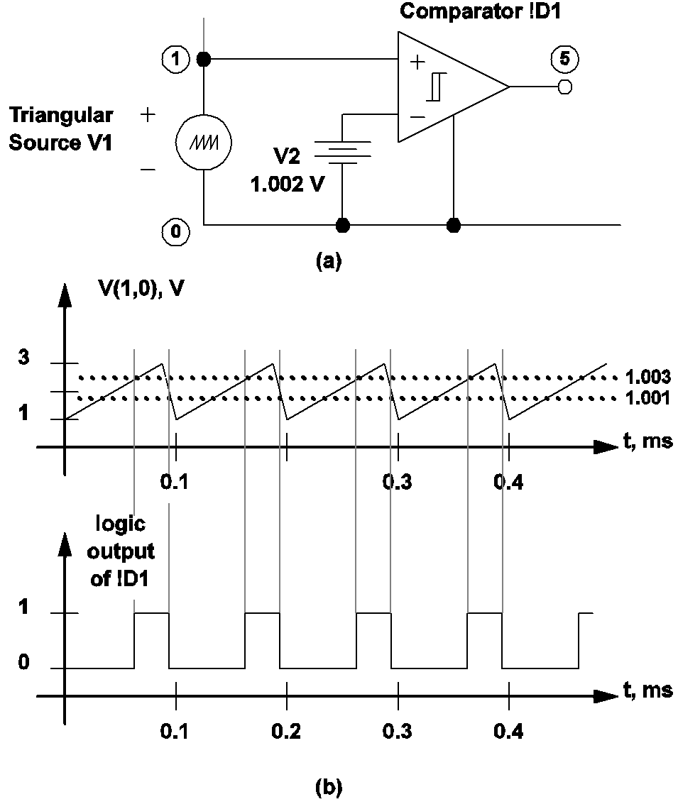 |
10.1 (a) A periodic triangular source, a battery, and a comparator used to define the start of a switching cycle, and (b) Output of the comparator in relationship to the differential voltage V(1,0). |
Definition of the Start of A Switching Cycle for a Self-Oscillating System
In the case of a self-oscillating system, the start of a switching cycle should be defined to coincide with a major switching event such as the on/off switching of the main power transistors(s) of a self-oscillating converter. Fig 10.2 (a) shows a small section of a hypothetical self-oscillating switching system. The main switching transistor Q1 is controlled by the control unit U1 through the base drive circuit B1. The output level of U1 is equal to 12 V and 0 V, respectively, when it is trying to switch the transistor Q1 on and off. In this case, the start of a switching cycle is best defined in terms of the transition of the output of U1. The comparator !D2 in this figure serves this purpose and the input statements defining !D2 and the .POP analysis may look as follows:
!D2 101 0 102 103 M2 IC=0
.MODEL M2 COMP RIN=10MEG ROUT=8 HYSTWD=10
+ VOH=5 VOL=0
V6 103 0 DC 6
.POP TRIG_GATE=!D2 TRIG_COND=0_TO_1 MAX_PERIOD=200U
With these input statements, the output of the logic gate !D2 is equal to logic 1 and logic 0, respectively, when the output of U1 is above 11 V and below 1 V. When the output of U1 is between 1 V and 11 V, the output state of !D2 remains unchanged. Fig 10.2 (b) illustrates the relationship between the output state of U1 and the output state of !D2. From this figure, it can be deduced that the start of a switching cycle is now recognized to occur when the output of U1 is rising and equal to 11 V. The output of U1 as shown in Fig 10.2 (b) has finite-time transitions when it switches between 0 V and 12 V. If U1 is a SIMPLIS logic gate, we can use U1 instead of an additional logic gate as the triggering gate for the POP analysis.
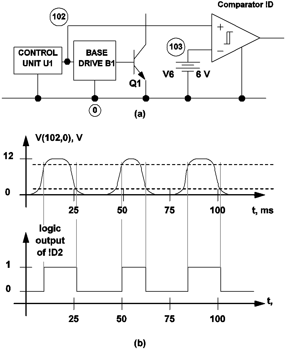 |
10.2 (a) A sample circuit used to define the start of a switching cycle for a variable-frequency switching system, and (b) Output of the comparator !D2 in relationship to the waveform of the voltage V(102,0). |
Definition of the Maximum Period
Depending on how the triggering gate and triggering condition are defined and depending on the capacitor voltages and inductor currents of the system, it is possible that the system either takes a very long time or is never able to reach a condition that triggers the start of a new switching cycle. Such a condition can occur at the start of the periodic operating point analysis or in the middle of a periodic operating point analysis. Since the triggering condition never occurs, one of the time-domain transient analyses mentioned in 10.2.1.1 may run forever. To avoid such a situation, the maximum simulation time for all POP time-domain transient analyses is set to the numerical value of the maximum period parameter. For example, a .POP statement such as
.POP TRIG_GATE=!D2 TRIG_COND=0_TO_1 MAX_PERIOD=500U
instructs SIMPLIS to carry out each of these transient analyses for a maximum duration of 500 microseconds. If the simulation time of a POP transient analysis reaches 500 microseconds without triggering the start of a new switching cycle, SIMPLIS will print out an error message and exit.
For a driven system, the maximum period should be set to at least three times the expected period. For a self-oscillating system, the maximum period should be set to about 10 times the longest period expected.
There are several reasons that SIMPLIS may fail to find a triggering condition for the system under study within the set maximum period. One is an error in the definition of the triggering condition. Given correctly defined triggering conditions, it is also possible that the transients resulting from the initial conditions specified for the system would prevent the system from reaching the triggering condition within the set maximum period. Usually, a regular time-domain transient analysis would reveal the reasons that the system failed to trigger the start of a new switching cycle.
Behaviour of POP Analysis after POP Convergence Failure
There are two choices of action that SIMPLIS will take when POP fails to converge. These are:
- Abort the run and output an error message. The error is written to a file but will also be displayed in the command shell message box. This action is taken if the .POP parameter TD_RUN_AFTER_POP_FAILS is set to zero.
- Start a time-domain (transient) analysis. The initial conditions for this time-domain analysis will be exactly the same as the initial conditions used for the POP run and will continue for a period controlled by the TD_RUN_AFTER_POP_FAILS parameter on the .POP line. See .POP Statement for POP Analysis for details. If a normal time-domain analysis had been specified to proceed after POP (for example, because a load transient study was being performed), then this time-domain analysis will proceed normally as if the POP analysis had converged successfully. This mode of operation makes it possible to study the load or line transient behaviour of systems for which POP convergence is difficult. Examples are systems running at very light load whereby they enter a pulse frequency mode of operation. Such systems do not have a well-defined steady state which makes POP convergence almost impossible. But by running a long enough time domain analysis before applying load or line stimuli, a near-steady-state condition may be reached. If no time-domain analysis had been specified after the POP analysis, the data generated during the additional time-domain analysis will be saved so that a diagnosis of the causes of POP convergence failure may be performed.
Options Associated with POP Analysis
There are five options associated with the periodic operating point analysis and they can be specified through the .OPTIONS statement explained in Option Statements. The options are specified in the form of
.OPTIONS opt1 opt2 ...where opt1, opt2, and ..., are various options recognized by SIMPLIS. The five options associated with the periodic operating point analysis and their meanings are listed below.
| POP_SHOWDATA | Shows the progress of the periodic operating point analysis. The default is not to show the progress. In general, this option is turned on as a debugging aid if a POP analysis fails. |
| POP_ITRMAX=n | Sets the maximum number of iterations for the periodic operating point analysis. "POP_ITRMAX=" is the eleven-character keyword "POP_ITRMAX=". n is a positive integer between 1 and 100. The default value for n is 20. |
| POP_CONVERGENCE=value | Sets the convergence criteria for the periodic operating point analysis. The convergence criteria is satisfied when the relative change in each state variable, between the start and end of a switching cycle, is less than this parameter. "POP_CONVERGENCE=" is the eleven-character keyword "POP_CONVERGENCE=". value is a positive floating point number between 1.0e-06 and 1.0e-14, inclusive. The default value for n is 1.0e-14. Note: During the POP analysis, the maximum relative change in the state variables is reported in percentages, while the POP_CONVERGENCE parameter is entered in actual value. |
| POP_USE_TRAN_SNAPSHOT | This option instructs POP to take advantage of the last data point of a previous transient simulation, assuming the circuit and the initial conditions remained the same between the two simulation runs. This option does not take on any value. It is either turned ON or turned OFF. If it is turned ON, the POP analysis will use the last data point of a previous transient simulation as the initial condition to start the POP analysis. Usually this leads to a faster POP analysis. Example: .OPTIONS POP_USE_TRAN_SNAPSHOT |
| POP_OUTPUT_CYCLES=n | Number of cycles of steady-state POP Data to show. After a successful POP analysis, SIMPLIS will generate the steady-state time-domain waveforms for an integral number switching cycles. If set, the option value must be a positive integer between 1 and 16, inclusively. If this option is not set, it defaults to 5. Example: .OPTIONS POP_OUTPUT_CYCLES=3 |
The POP_ITRMAX option puts a limit on the number of iterations of the periodic operating point analysis that will be carried out by SIMPLIS. When the periodic operating point analysis fails to converge to a steady-state solution after this limit is reached, SIMPLIS prints out an error message and exits.
| ◄ Overview | Synopsis of the Periodic Operating Point Analysis ▶ |