Pull Up/Down Resistors
The pull resistors in the libraries are organized in banks. A single bank of pull resistors can be made up of one to 32 pull resistors. The entire bank of pull resistors can be configured to be pull-up or pull-down resistors through the edit dialog. When used as pull-up resistors, the unexposed terminals of the resistors are set to a HIGH (1) logic level during the simulation. When used as pull-down resistors, the unexposed terminals of the resistors are set to a LOW (0) logic level during the simulation.
Strictly speaking, pull resistors have no output pins but just pins for the exposed terminals of the pull resistors. For the sake of generality in the discussion, the pins of the pull resistors are quite often referred to as “output pins” in our documentation.
In this topic:
| Model Name: | Pull Resistor | |||
| Simulator: | This device is compatible with the SIMPLIS simulator. | |||
| Parts Selector Menu Location: | ||||
| Symbol Library: | None - the symbol is automatically generated when placed or edited. | |||
| Model Library: | None - the model is automatically generated when the simulation is run. | |||
| Subcircuit Names: |
|
|||
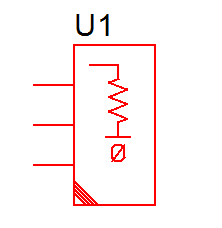
| Symbol: |
|
|||
| Multiple Selections: | Only one device at a time can be edited. | |||
Editing the Pull Resistor
To configure the Pull Resistor, follow these steps:
- Double click the symbol on the schematic to open the editing dialog to the Parameters tab.
- Make the appropriate changes to the fields described in the table below the image.
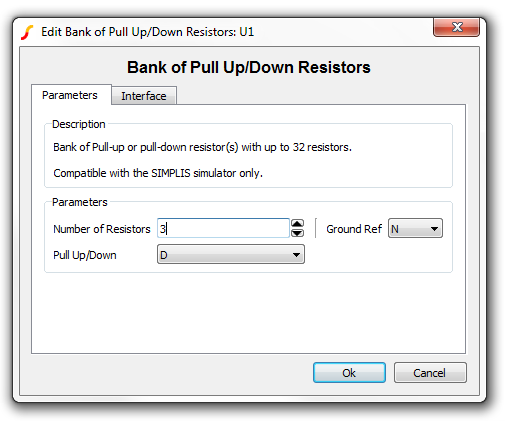
| Label | Parameter Description |
| Ground Ref | Determines whether or not a device has a ground reference pin. Any digital component that has an input or output pin connected to an analog circuit node must have its Ground Ref pin connected to an analog node. This is usually the ground on the schematic. |
| Number of Resistors | Number of pull resistors grouped together |
| Pull Up/Down | Pull Direction. 'U' for pull-up resistors and 'D' for pull-down resistors. |
To define the parameters for the interface between this digital component and each analog component connected directly to an output pin, follow these steps:
- From the Edit Pull Resistor dialog box, click on the Interface tab.
- Make the appropriate changes to the fields described in the table below the image.
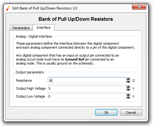
| Label | Parameter Description | |
| Resistance | Resistance of each pull resistor pin | |
| Output High Voltage | Output high voltage for each pull resistor pin | |
| Output Low Voltage | Output low voltage for each pull resistor pin | |
Examples
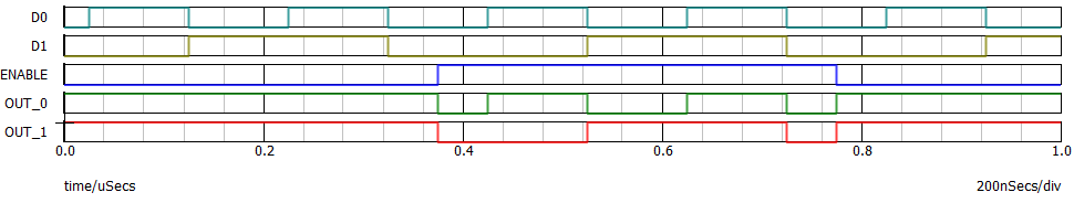
The test circuit used to generate the waveform examples in the next section can be downloaded here: simplis_pull_resistor_example.sxsch.
Waveforms
The waveforms below were taken from the simplis_pull_resistor_example.sxsch schematic, which involves a bank of two tri-state buffers and a bank of two pull-up resistors. When the tri-state buffers are enabled, the output strengths of its output pins dominate over the RESISTIVE strengths of the pull-up resistors and thus the logic levels of the corresponding output nodes follow those of the input nodes of the tri-state buffers. When the tri-state buffer is disabled, the RESISTIVE strengths of the pull-up resistors dominate the HIGH-IMPEDANCE strengths of the output pins of the tri-state buffers and thus the logic levels of the concerned output nodes are all equal to HIGH (1).
Subcircuit Parameters
Because the model for the pull resistors is generated by a template script when the simulation is executed, a hand-coded model cannot be inserted into a netlist. The template script for this device is simplis_make_pull_resistor_model.sxscr. The following parameter table defines the parameters used in this model.
| Parameter Name | Label | Data Type | Range | Units | Parameter Description | |
| GNDREF | Ground Ref | String |
|
none | Determines whether or not a device has a ground reference pin. Any digital component that has an input or output pin connected to an analog circuit node must have its Ground Ref pin connected to an analog node. This is usually the ground on the schematic. | |
| NUM_RESISTORS | Number of pull resistors | Integer | 1 to 32 | none | Number of pull resistors grouped together | |
| RESISTANCE | Resistance | Number | min: 1m | Ω | Resistance of each pull resistor pin | |
| VOH | Output High Voltage | Number | any | V | Output high voltage for each pull resistor pin | |
| VOL | Output Low Voltage | Number | any | V | Output low voltage for each pull resistor pin | |