1.0.3 Multi-Level Modeling
Multi-Level models are a key feature of SIMPLIS. Multi-Level models use a single parameter to configure the model complexity. The multi-level modeling concept allows models to be tailored to the application, where minimum model complexity is used for the simulation objective, which in turn results in the fastest simulations. In this topic you will learn about two types of multi-level models: multi-level MOSFETs and multi-level capacitors.
In this topic:
Key Concepts
This topic addresses the following key concepts:
- Multi-Level models are configured with a single parameter.
- The schematic-view of the model changes based on the model level parameter.
- The model level is chosen based on the desired simulation objective.
What You Will Learn
In this topic, you will learn the following:
- How models can be configured with different levels of complexity with a single parameter.
- How to choose the appropriate level based on your simulation objective.
Getting Started: Multi-Level MOSFET Model
- Open the schematic titled 1.1_SelfOscillatingConverter_POP_AC_Tran.sxsch.
- Double click on the MOSFET Q1. Result: The Extract MOSFET Dialog opens. The Model level parameter control is shown below:
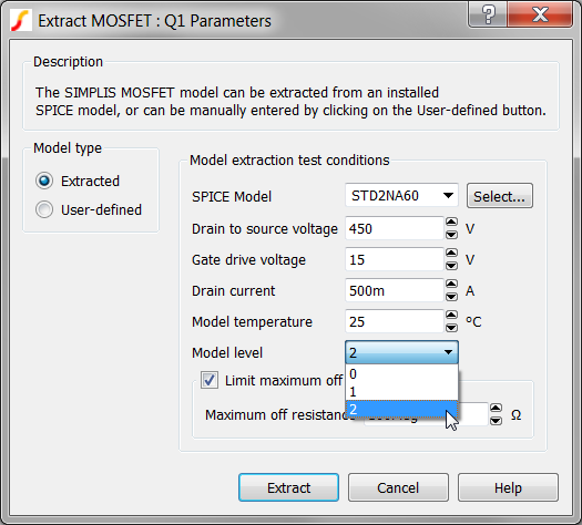
- Click on the Help Button in the lower right corner of the dialog. Result: The Help system opens to the SIMPLIS MOSFET Models topic.
Discussion: Multi-Level Modeling
At this point, you should have the Extract MOSFET Dialog open in SIMetrix/SIMPLIS and the SIMPLIS MOSFET Models help topic open in a browser window.
MOSFETs, in common with the other semiconductors such as Diodes, Zener Diodes, IGBTs and JFETs have very nonlinear behavior. For example, the drain-to-source capacitance of a MOSFET can radically change as the voltage across the MOSFET changes from the blocking to the conducting state. If you are interested in the switching behavior of this device, it is important to model this capacitance change; However, if you primarily interested in the Bode Plot of the converter, the details of the switching transition are typically not important.
SIMPLIS has the ability to change both the underlying schematic structure and the parameters of a model based on a single parameter value. In the Extract MOSFET Dialog, and indeed, in many SIMPLIS built-in models, the "Level" or "Model Level" parameter controls the schematic view of the model which is used in the simulation.
Multi-Level Model Example #1: The SIMPLIS MOSFET
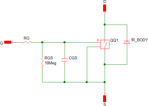
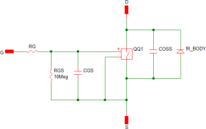
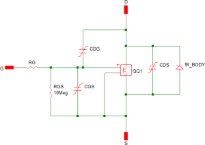
The MOSFETs used in SIMPLIS have four levels of complexity. Each level is described in detail in the currently open help topic. Below are the schematic views of the level 0 , 1, and 2 models. The level 3 model is intended for user-customized models, and is not supported by the internal model extraction routines.
| Level 0 Model | Level 1 Model | Level 2 Model | ||||||||||||||||||||||||||||||||||||
|
|
|
||||||||||||||||||||||||||||||||||||
|
|
|
The Level 0 MOSFET is used whenever the detailed switching action of the MOSFET is not important. The Level 2 MOSFET, which models the nonlinear capacitances, is typically used when the switching transitions are important, such as when measuring efficiency. The Level 1 MOSFET is used for power stage development when the converter topology relies on the MOSFET output capacitance.
Model Parameter Extraction
- If you have closed the Extract MOSFET dialog, reopen it by double clicking on the MOSFET Q1.
- Click Extract. Result: A progress bar briefly displays the progress as SIMetrix/SIMPLIS extracts the SIMPLIS model parameters from the SPICE model.
- Look in the SIMetrix/SIMPLIS command shell window. Tip: You can press the space bar to bring the command shell into view.You should see the following message:
Extracting SIMPLIS model for STD2NA60. Please wait..
Complete
You have just executed several SIMetrix SPICE simulations on the SPICE model for the STD2N60 MOSFET, curve-fit the SPICE simulation data to a SIMPLIS PWL model, and written 66 model parameters to the symbol. Congratulations! Nice work!
The Multi-Level Modeling concept is at the core of this process - that models can have varied complexity based on the application. You can maximize simulation speed by using the minimum model level required for your analysis.
As you have just seen, SIMetrix/SIMPLIS has the unusual ability to simulate SPICE semiconductor models and from these results to extract a PWL SIMPLIS model. This capability becomes especially powerful when you combine it with the Multi-Level Modeling concept. Now critical device models can have the appropriate level of complexity based on the simulation objective of a particular simulation run.
Multi-Level Model Example #2: The Multi-Level Capacitor
Passive components, such as inductors and capacitors are also available as multi-level models. The model level in this case determines the parasitic elements which are included in the model. In this section the new Multi-Level capacitor is used as an example. This capacitor was introduced with SIMetrix/SIMPLIS version 8.0, and replaces the old electrolytic capacitor.
Exercise #2: Multi-Level Capacitor Model
- Double click on the output capacitor C1. This is the first capacitor
symbol to the right of the transformer output. Result: The Edit Multi-Level Capacitor dialog opens:
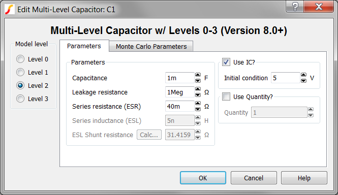
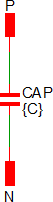
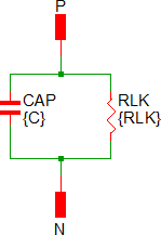
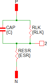
SIMetrix/SIMPLIS has two multi-level capacitor models; the one used here has model levels 0-3, and a second, more detailed model, has levels 4 and 5. The three multi-level capacitors on this schematic all use the new multi-level capacitor model with levels 0-3 and have the model level set to 2. Equivalent schematic images of the level 0-3 models are shown below:
| Level 0 | Level 1 | Level 2 | Level 3 | ||||||||||||||||||||||
|
|
|
|
||||||||||||||||||||||
|
|
 |
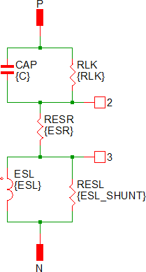 |
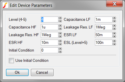
The Level 4-5 model for the electrolytic capacitor models the low and high frequency components separately. The model is essentially two electrolytic capacitors in parallel. The edit dialog for the Level 4-5 electrolytic capacitor is shown below:
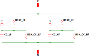
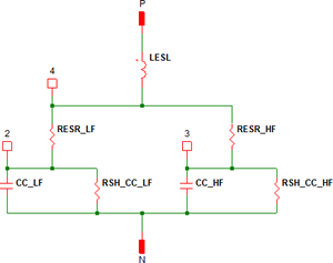
The schematic views of the level 4 and level 5 models are shown below. The Level 5 model adds a Equivalent Series Inductance (ESL) to the Level 4 model.
| Level 4 | Level 5 | ||||||||||||||||||||||||||
|
|
||||||||||||||||||||||||||
|
|
For future reference, you can place the Multi-Level Capacitors from the SIMPLIS parts selector:
- Commonly Used Parts>Multi-Level Capacitor (Level 0-3 w/Quantity) (Version 8+)
- Commonly Used Parts>Electrolytic Capacitor (w/ HF ESR and ESL) (Level 4 - 5)
Conclusions and Key Points to Remember
- Multi-Level modeling is extremely powerful because:
- A multi-level model is a flexible model. The model can range from simple to extremely complex based on the level parameter. The schematic view of the model can change based on the level parameter.
- The user can select the minimum complexity which meets the current simulation objective.
- By enabling one component symbol to have different underlying models the user can have a single schematic serve multiple simulation objectives. This can save a lot of time and confusion compared with having to manage multiple versions of the same schematic.
- All semiconductors used in SIMPLIS are modeled with PWL devices. To determine what level of model is used, double click on the symbol and note the value of the model level parameter. Using the lowest complexity model level consistent with the required accuracy of the simulation objective will increase simulation speed.
- In Module 6 - Modeling you will learn how to create your own multi-level models. During the training course, think about what kind of models you have used which would benefit from the multi-level modeling concept.
- In SIMPLIS, the parameter name "Level" is used to describe the level of complexity
of any given model. There is nothing special about this name, and you can build your
own models with any parameter name you would like. For example, an IC model may have
a "Process" parameter or a "Corner" Parameter. The Process might have three string
values. The model could then have the string value configure the model:
- 'Slow'
- 'Typical'
- 'Fast'