Sampler and Zero-Order Hold
The Sampler and Zero-Order Hold models an analog sample and hold. On each clock edge, the input voltage is sampled and held until the next clock edge. As with the other devices in the Discrete Time Filter category, the Sampler and Zero-Order Hold is compatible with the SIMPLIS POP and AC analyses.
The information in this topic refers to the latest Sampler and Zero-Order Hold which was introduced in version 8.10. In versions prior to 8.10, a similar Sampler and Zero Order Hold exists and has the same behavior as the new version. The new version is implemented in a library file as opposed to a templatescript, but the electrical behavior is identical. If you require a sample/hold for use in versions prior to 8.10, the old Sampler and Zero-Order Hold can be placed from the part selector location: .
Related topics:
In this topic:
| Model Name: | Sampler and Zero-Order Hold | |||
| Simulator: | This device is compatible with the SIMPLIS simulator. | |||
| Parts Selector Menu Location: | ||||
| Symbol Library: | simplis_discrete_time_filters.sxslb | |||
| Model Library: | simplis_discrete_time_filters.lb | |||
| Subcircuit Name: | SIMPLIS_DTF_SNH_Y__V2 | |||
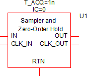
| Symbol: |
|
|||
| Multiple Selections: | Only one device at a time can be edited. | |||
Editing the Sampler and Zero Order Hold
To configure the Sampler and Zero Order Hold, follow these steps:
- Double click the symbol on the schematic to open the editing dialog to the Parameters tab.
- Make the appropriate changes to the fields described in the table below the image.
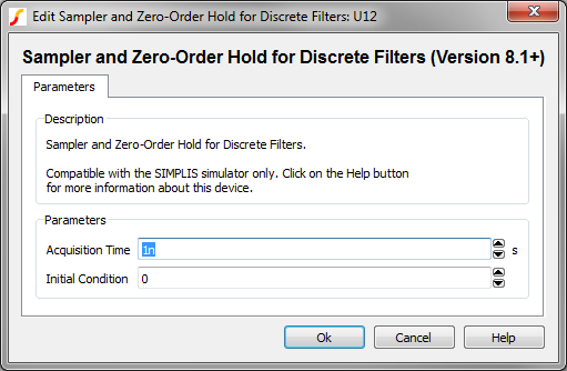
| Label | Parameter Description |
| Acquisition Time | Filter acquisition time in seconds |
| Initial Condition | Initial condition of the Sampler and Zero Order Hold output at time=0 |
Examples
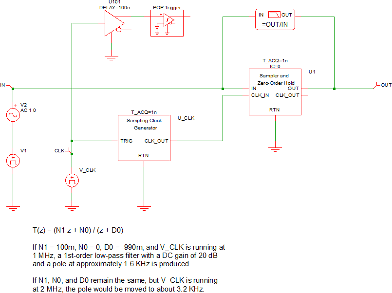
The test circuit used to generate the waveform examples in the next section can be downloaded here: simplis_036_samplehold_example.sxsch.
Waveforms
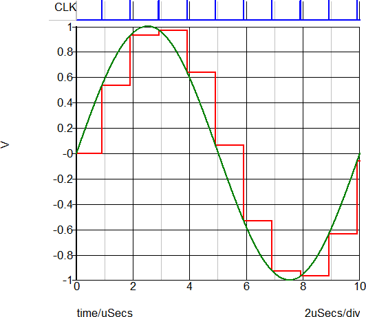
In the circuit example, a 100kHz sine wave with a 1V amplitude ( +/- 1V peak ) is applied to the input of the sampler and hold. The clock has a frequency of 1MHz, and the sampled input voltage is output on the same graph as the input voltage.
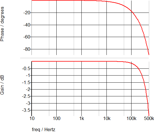
The following AC waveforms confirm that the DC gain is 0dB and the phase change at 1/2 the sampling frequency is the expected 90 degrees.
Subcircuit Parameters
The subcircuit parameter names, data types, ranges, units, and descriptions are in the following table. The parameter names can be used to generate netlist entries for the device. For example, a valid Sampler and Zero-Order Hold netlist entry would be:
X$U1 27 32 0 31 0 SIMPLIS_DTF_SNH_Y__V2 vars: IC=0 T_ACQ=1n
| Parameter Name | Label | Data Type | Range | Units | Parameter Description |
| IC | Initial Condition | Number |
|
none | Initial condition of the Sampler and Zero Order Hold output at time=0 |
| T_ACQ | Acquisition Time | Number | min: 1f | s | Filter acquisition time in seconds |